
FGD Electrical & C&I Engineering: Scope, Deliverables and Design Requirements
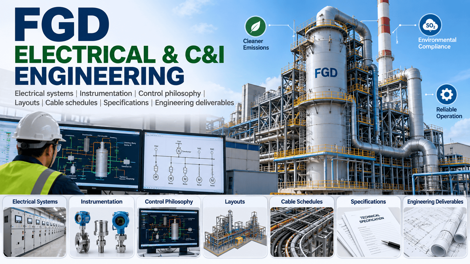
Understand FGD electrical and C&I engineering scope, including electrical systems, instrumentation, control philosophy, layouts, cable schedules,Specifications and engineering deliverables.
Introduction
Flue Gas Desulfurization, commonly known as FGD, has become an important emission-control system for coal-fired thermal power plants. The successful implementation of an FGD package is not limited to selecting a scrubber, absorber, pumps, fans, tanks or reagent-handling equipment. The electrical, instrumentation and control systems are equally important because they provide the power supply, measurement, automation, protection, interlocking and operational visibility required for reliable FGD operation.
This is why FGD electrical and C&I engineering requires close coordination between process, mechanical, electrical, instrumentation, control, civil, structural, piping and plant-interface engineering.
An FGD system typically contains a large number of electrically driven loads, including slurry pumps, oxidation air blowers, limestone preparation equipment, gypsum dewatering equipment, agitators, fans, conveyors, dosing systems, valves and auxiliary systems. These loads must be integrated with the existing power plant electrical network while maintaining appropriate availability, protection, maintainability and operational flexibility.
At the same time, the C&I system has to monitor and control critical parameters such as flue-gas flow, pressure, temperature, slurry flow, pH, density, tank levels, differential pressure, SO₂ concentration, pump status and valve positions.
The engineering challenge becomes even more significant when FGD is installed as a brownfield retrofit. Engineers must work around existing plant equipment, limited space, existing cable routes, operating constraints, shutdown windows and established DCS/PLC architectures.
In India, the importance of FGD projects is closely associated with thermal power plant emission compliance. Government information has documented extensive FGD deployment across coal-based generating units, with hundreds of units identified for installation or implementation. Power Ministry
For project owners, EPC contractors, FGD technology suppliers and engineering organizations, the quality of the electrical and C&I engineering package can directly affect procurement, construction, commissioning and long-term plant reliability.
This comprehensive guide explains the scope of FGD electrical engineering, FGD C&I engineering, basic engineering, detailed engineering, design deliverables, control philosophy, cable engineering, instrumentation, PLC/DCS interfaces and common execution challenges.
1. What Is FGD?
1.1 Understanding Flue Gas Desulfurization
Flue Gas Desulfurization is an emission-control technology used to reduce sulfur dioxide (SO₂) from flue gas generated during combustion, particularly in coal-fired thermal power plants.
The U.S. Environmental Protection Agency identifies FGD systems as a principal means of controlling SO₂ emissions from coal-fired electricity-generating units. Wet FGD systems are widely used, although dry and other configurations also exist. US EPA
In a typical wet limestone FGD system, flue gas passes through an absorber where it comes into contact with an alkaline limestone slurry. SO₂ reacts with the slurry and is converted into chemical compounds that can ultimately form gypsum in forced-oxidation configurations.
A simplified process chain can be represented as:
Boiler → ESP/Particulate Control → FGD Booster/ID Fan Interface → Absorber → Mist Eliminator → Stack
The supporting systems may include:
- Limestone receiving
- Limestone crushing
- Limestone grinding
- Limestone slurry preparation
- Limestone slurry storage
- Absorber circulation
- Oxidation air
- Gypsum dewatering
- Wastewater handling
- Process water
- Instrument air
- Service air
- Drainage
- Electrical power supply
- Control and automation
- Emission monitoring
Each of these systems creates electrical and C&I requirements.
1.2 Why Electrical and C&I Engineering Matters
A mechanical FGD package can be technically well designed but still experience operational problems if the electrical and control systems are not properly engineered.
For example:
- An undersized motor can cause operational limitations.
- Poor cable routing can create installation difficulties.
- Incorrect protection settings can lead to unnecessary trips.
- Inadequate instrumentation can reduce process visibility.
- Poorly designed interlocks can cause unsafe equipment operation.
- Incomplete DCS interfaces can delay commissioning.
- Inadequate redundancy can reduce system availability.
- Incorrect instrument ranges can affect process control.
- Poor alarm management can overload operators.
- Incomplete cause-and-effect logic can create commissioning problems.
Therefore, FGD electrical and C&I engineering should be developed as an integrated engineering package rather than as independent disciplines.
2. Role of Electrical Engineering in FGD
Electrical engineering provides the power infrastructure required to operate the FGD plant.
The electrical scope generally begins with the development of the load list and power philosophy and extends through:
- Power distribution
- Transformers
- MV/LV switchgear
- MCCs
- VFDs
- Motors
- UPS systems
- DC systems
- Emergency power
- Protection
- Earthing
- Lightning protection
- Cable systems
- Illumination
- Small power
- Electrical layouts
- Equipment specifications
- Electrical calculations
- Testing and commissioning support
A good FGD electrical engineering package must consider both the FGD process requirements and the existing thermal power plant electrical system.
2.1 Major Electrical Loads
Typical FGD electrical loads may include:
Absorber system
- Recirculation pumps
- Agitators
- Oxidation air blowers
- Mist eliminator wash pumps
- Drain pumps
Limestone system
- Crushers
- Conveyors
- Grinding mills
- Feeders
- Bucket elevators
- Slurry pumps
- Agitators
Gypsum system
- Hydrocyclones
- Vacuum pumps
- Belt filters
- Conveyors
- Wash-water pumps
- Agitators
Auxiliary systems
- Ventilation fans
- HVAC equipment
- Drainage pumps
- Water pumps
- Air compressors
- Lighting
- Small power
- Crane systems
- Hoists
The load list should identify equipment tag, service, rating, voltage, starting method, operating duty, standby philosophy and other relevant design information.
3. Role of C&I Engineering
C&I means Control and Instrumentation.
FGD C&I engineering converts the process requirements into a measurable and controllable system.
The C&I engineer must understand:
- What needs to be measured?
- Why does it need to be measured?
- What range should be measured?
- What happens when the parameter moves outside its normal range?
- Should the parameter be alarmed?
- Should it initiate an interlock?
- Should the equipment trip?
- Should the value be displayed on DCS/PLC?
- Is redundancy required?
- What is the failure response?
The instrumentation and control system therefore becomes the operational interface between the FGD process and plant operators.
The ISA-5.1 framework is specifically intended to provide consistent instrumentation symbols and identification practices, including applications in power generation. isa.org
For fossil-fuel power plants, the ISA-77 series provides guidance covering automation, control and safe operation, including sequence control, instrumentation installation, HMI and plant-control topics. isa.org
ISA Standards – Instrumentation and Control
4. FGD Electrical System Architecture
The electrical architecture depends on plant voltage levels, existing switchgear configuration, FGD capacity and project-specific availability requirements.
A simplified arrangement can be:
Existing Plant Auxiliary Supply
↓
FGD Auxiliary Transformer
↓
MV Switchgear
↓
MCC / Distribution Boards
↓
VFDs / Starters
↓
Motors and Electrical Loads
Additional systems may include:
UPS → PLC/DCS/Control System
and
Battery + DCDB → Protection, Control and Emergency Loads
The electrical design should establish:
- Source philosophy
- Normal supply
- Emergency supply
- Standby supply
- Voltage levels
- Short-circuit levels
- Transformer capacity
- Switchgear ratings
- Motor starting philosophy
- Protection philosophy
- Metering
- Synchronization/interface requirements
- Earthing
- Lightning protection
- Cable routing
5. FGD Load List
The FGD load list is one of the fundamental electrical engineering documents.
It should be developed early because numerous downstream calculations depend on it.
5.1 Typical Load List Information
A detailed load list may contain:
| Parameter | Typical Information |
|---|---|
| Equipment Tag | FGD-P-001 |
| Equipment Description | Absorber Recirculation Pump |
| Motor Rating | kW |
| Voltage | V |
| Frequency | Hz |
| Quantity | Nos. |
| Running Duty | Continuous/Intermittent |
| Standby | Yes/No |
| Starting Method | DOL/VFD/Soft Starter |
| Power Factor | Vendor/project value |
| Efficiency | Vendor/project value |
| Normal Load | kW |
| Starting Load | As applicable |
| MCC | Identified MCC |
| Area | FGD Area |
| Cable | Preliminary/Final |
| Control | Local/Remote |
| Criticality | Critical/Non-critical |
The load list should be continuously updated as vendor data and equipment selections become available.
5.2 Connected Load and Maximum Demand
The engineering team should distinguish between:
- Connected load
- Running load
- Maximum demand
- Standby load
- Intermittent load
- Emergency load
- Essential load
This distinction is important when sizing transformers, switchgear, generators and auxiliary supplies.
A poor load assessment can lead either to:
- Oversized electrical infrastructure and unnecessary CAPEX, or
- Undersized infrastructure and operational reliability problems.
6. SLD Development
The Single Line Diagram (SLD) is a key document in FGD electrical design.
The SLD provides a simplified representation of the electrical distribution system and allows engineers, owners and EPC contractors to understand the power architecture.
A typical FGD SLD may show:
- Incoming supply
- Transformer
- MV switchgear
- Bus sections
- Bus coupler
- MCC
- VFD panels
- Emergency supply
- UPS
- DC system
- Capacitor banks where applicable
- Major motor feeders
- Protection devices
- Metering
- Cable connections
6.1 Electrical Design Considerations
The SLD should be coordinated with:
- Plant electrical philosophy
- FGD process requirements
- Motor ratings
- Transformer capacity
- Short-circuit study
- Protection study
- Load-flow study
- Motor starting study
- Reliability philosophy
- Vendor requirements
For retrofit projects, the interface with existing switchgear must be carefully assessed.
7. Cable Engineering
Cable engineering is one of the largest components of detailed FGD electrical engineering.
A typical FGD project may contain extensive:
- Power cables
- Control cables
- Instrument cables
- Communication cables
- Fiber-optic cables
- Special-purpose cables
Cable engineering includes:
- Cable sizing
- Cable selection
- Voltage-drop calculations
- Short-circuit withstand
- Ampacity
- Derating
- Installation method
- Cable routing
- Cable tray selection
- Cable schedule
- Termination schedule
- Gland selection
- Cable drum schedule
- Cable tray layout
7.1 Cable Sizing
Cable sizing should consider:
- Full-load current
- Installation method
- Ambient temperature
- Grouping
- Soil thermal resistivity for buried cables
- Voltage drop
- Short-circuit withstand
- Starting current
- Continuous loading
- Future margin
- Applicable standards
Motor cables require particular attention because motor starting can produce higher current and temporary voltage drop.
7.2 Cable Schedule
A detailed cable schedule generally includes:
- Cable number
- From equipment
- To equipment
- Cable type
- Number of cores
- Core size
- Length
- Route
- Drum number
- Gland type
- Termination type
- Service
- Voltage level
A properly coordinated cable schedule helps procurement, installation and commissioning teams.
8. Earthing and Lightning Protection
FGD plants operate in industrial environments containing large mechanical structures, metallic tanks, piping, electrical equipment and instrumentation.
The earthing system should provide:
- Personnel safety
- Equipment protection
- Fault-current return path
- Static discharge
- Instrument reference
- Lightning-current dissipation
The engineering package can include:
- Earth grid
- Equipment earthing
- Motor earthing
- Transformer neutral earthing
- Switchgear earthing
- Cable tray bonding
- Structure bonding
- Instrument earth
- Clean earth where required
- Lightning protection system
The detailed design must account for the project’s applicable electrical standards and the plant’s existing earthing philosophy.
9. Instrumentation Design for FGD
Instrumentation is central to FGD process control.
The process contains several critical variables that must be continuously measured.
Typical measurements include:
- Pressure
- Differential pressure
- Temperature
- Flow
- Level
- Density
- pH
- Conductivity
- SO₂ concentration
- Oxygen concentration
- Vibration
- Motor current
- Valve position
- Equipment status
9.1 Pressure Instrumentation
Pressure transmitters may be required at locations such as:
- Flue gas inlet
- Flue gas outlet
- Absorber
- Ducts
- Slurry lines
- Air systems
- Pumps
- Filters
Differential pressure measurement can be important for monitoring:
- Mist eliminators
- Filters
- Duct sections
- Scrubber pressure drop
9.2 Temperature Measurement
Temperature instruments can be provided for:
- Inlet flue gas
- Outlet flue gas
- Slurry
- Process water
- Bearing temperature
- Motor temperature
- Equipment protection
Temperature measurement is particularly important when equipment operating limits are sensitive to process conditions.
9.3 Flow Measurement
Flow measurement can include:
- Limestone slurry flow
- Absorber recirculation flow
- Oxidation air
- Process water
- Wash water
- Gypsum slurry
- Wastewater
- Instrument/service water
Flow measurement technologies should be selected according to fluid characteristics.
For abrasive or slurry services, instrument selection requires special consideration of:
- Solids content
- Particle size
- Conductivity
- Velocity
- Lining
- Electrode material
- Maintenance accessibility
10. pH Measurement in FGD
pH is one of the important process parameters in wet FGD systems.
The absorber chemistry must be maintained within the required operating range to achieve appropriate SO₂ removal performance while managing reagent consumption and downstream chemistry.
A pH measurement system can include:
- pH sensor
- Probe assembly
- Sample arrangement
- Transmitter
- Local indication
- DCS indication
- Calibration facilities
The engineering design must consider the actual process environment because slurry service can be challenging for sensors.
Instrument accessibility, cleaning, calibration and replacement should therefore be considered during layout design.
11. Density and Solids Measurement
FGD slurry characteristics influence process performance.
Density or solids concentration measurements may be used for:
- Limestone slurry
- Absorber slurry
- Gypsum slurry
The selected technology must be compatible with slurry characteristics and process requirements.
Instrumentation engineers should review:
- Accuracy
- Range
- Abrasion
- Fouling
- Maintenance
- Calibration
- Process connection
- Installation orientation
12. SO₂ and Emission Monitoring
SO₂ measurement is fundamental to the environmental performance of the FGD system.
Depending on the project configuration, emission monitoring may involve:
- SO₂ analyzer
- O₂ analyzer
- Flue-gas temperature
- Flow
- Pressure
- Moisture
- Other parameters specified by applicable regulatory requirements
The interface between FGD controls and plant emission monitoring must be clearly defined.
In India, emission compliance requirements should be established against the latest applicable MoEF&CC/CPCB requirements and project-specific regulatory conditions rather than relying solely on generic FGD design assumptions. Government and CEA publications provide important reference material for thermal power plant emission control and FGD retrofit projects. Press Information Bureau
Central Electricity Authority – Thermal Engineering & Technology Development
13. FGD Control Philosophy
The control philosophy defines how the FGD plant should operate.
It explains:
- Normal operation
- Startup
- Shutdown
- Emergency shutdown
- Automatic control
- Manual operation
- Equipment sequencing
- Standby changeover
- Interlocks
- Trips
- Alarms
- Operator actions
A well-developed FGD control system engineering philosophy should be prepared before detailed PLC/DCS programming.
13.1 Automatic Control
Typical automatic control loops may include:
Absorber pH control
The pH signal can be used to influence reagent/slurry addition or related process control actions.
Slurry flow control
Flow may be controlled according to process demand.
Tank level control
Tank levels can be controlled by modulating inlet/outlet flows or starting/stopping pumps.
Pressure control
Duct or process pressure can be monitored and controlled according to the system design.
Oxidation air control
Oxidation air may be controlled based on process requirements.
14. PLC/DCS Interface
Modern FGD systems may use a dedicated PLC, DCS-based control architecture or another plant-approved automation configuration.
The final architecture depends on:
- Existing plant DCS
- FGD vendor package
- Client specification
- Cybersecurity requirements
- Availability philosophy
- Interface requirements
- Plant standard
The interface may include:
- Analog inputs
- Analog outputs
- Digital inputs
- Digital outputs
- Modbus
- Ethernet-based communication
- Fiber-optic communication
- Hardwired signals
- Remote I/O
14.1 DCS Integration
The DCS interface should provide the operator with sufficient information to monitor and control the FGD system.
Typical information includes:
- Equipment status
- Motor status
- Valve status
- Process values
- Alarms
- Trips
- Interlocks
- Control outputs
- Equipment permissives
- Running hours
- Trends
- Diagnostic information
Interface documents should clearly define:
- Signal name
- Tag number
- Signal type
- Range
- Engineering unit
- Source
- Destination
- Normal state
- Alarm requirement
- Trip requirement
15. Interlocks and Logic
Interlocks protect equipment and prevent incorrect sequences.
For example, a pump may require:
- Adequate tank level
- Valve open
- No trip condition
- Electrical supply healthy
- Lubrication available
- Associated equipment available
Only after permissive conditions are satisfied should the equipment be allowed to start.
Similarly, a pump may automatically trip if:
- Low suction level occurs
- Motor protection operates
- Excessive vibration occurs
- Bearing temperature becomes abnormal
- Discharge pressure becomes unacceptable
The actual logic must always be based on the approved process design, vendor documentation, plant philosophy and safety requirements.
16. Cause-and-Effect Diagram
The Cause-and-Effect Matrix is one of the most important documents in FGD C&I engineering.
It links:
Cause → Logic → Action
For example:
| Cause | Logic/Condition | Action |
|---|---|---|
| Low Tank Level | Level below trip setpoint | Stop associated pump |
| High Motor Temperature | Temperature above trip limit | Motor trip |
| High Vibration | Vibration above trip limit | Equipment trip |
| Loss of Instrument Air | Pressure below setpoint | Alarm / predefined safe action |
| High Absorber DP | DP above limit | Alarm |
| Emergency Stop | ESD activated | Defined equipment shutdown |
The exact values and actions must be established through project engineering and approved documentation.
17. Equipment Specifications
Electrical and C&I engineering also supports preparation and review of equipment specifications.
Typical electrical specifications may cover:
- Motors
- MV switchgear
- LV switchgear
- MCC
- VFD
- Transformers
- UPS
- Batteries
- DC systems
- Distribution boards
- Lighting systems
- Cable systems
C&I specifications may cover:
- Transmitters
- Flow meters
- Pressure instruments
- Temperature instruments
- Level instruments
- pH analyzers
- Density meters
- Gas analyzers
- Control valves
- On/off valves
- PLC
- Remote I/O
- Marshalling cabinets
- Instrument junction boxes
- Control panels
18. FGD Basic Engineering
FGD basic engineering establishes the technical foundation for detailed engineering and procurement.
It typically includes:
- Design basis
- Process description
- Electrical philosophy
- C&I philosophy
- Load list
- Preliminary SLD
- Preliminary equipment list
- Preliminary instrument list
- Control philosophy
- Preliminary layouts
- Utility requirements
- Preliminary cable philosophy
- Preliminary earthing philosophy
- Preliminary specifications
- Major equipment data sheets
Basic engineering should establish enough information to control subsequent detailed design.
18.1 Design Basis
The design basis may address:
- Plant capacity
- Coal characteristics
- Sulfur content
- Flue-gas flow
- Flue-gas temperature
- SO₂ concentration
- Required outlet emissions
- FGD technology
- Availability
- Operating philosophy
- Environmental conditions
- Electrical supply
- Control system architecture
- Codes and standards
The design basis is particularly important for retrofit projects because the FGD system must be compatible with the existing plant.
19. FGD Detailed Engineering
FGD detailed engineering converts approved basic engineering into procurement-, construction- and commissioning-ready documents.
Typical deliverables include:
Electrical
- Final SLD
- Load list
- Transformer sizing
- Cable sizing calculations
- Cable schedule
- MCC schedule
- Switchgear specifications
- Motor datasheets
- VFD specifications
- Electrical equipment layouts
- Cable tray layouts
- Earthing layout
- Lighting layout
- Small-power layout
- Protection coordination
- Short-circuit calculations
- Load-flow calculations
- Voltage-drop calculations
C&I
- Instrument index
- I/O list
- Instrument datasheets
- Instrument location drawings
- Instrument hook-ups
- Cable schedule
- JB schedule
- Marshalling schedule
- Control philosophy
- Cause-and-effect matrix
- Logic diagrams
- Control narratives
- Alarm philosophy
- Interlock philosophy
- PLC/DCS interface list
- MTO/BOQ
- Control panel specifications
20. FGD Electrical and C&I Engineering Deliverables
A typical project deliverable register may include the following.
Electrical Engineering Deliverables
- Electrical design basis
- Electrical load list
- Motor list
- Transformer sizing calculation
- Transformer datasheet
- Switchgear datasheet
- MCC datasheet
- SLD
- Protection philosophy
- Protection coordination study
- Short-circuit calculation
- Load-flow study
- Motor starting study
- Cable sizing calculation
- Cable schedule
- Cable tray layout
- Earthing calculation
- Earthing layout
- Lightning protection design
- Lighting calculation
- Lighting layout
- Small-power layout
- Equipment layout
- Electrical room layout
- Junction box schedule
- Electrical BOQ
- Technical specifications
- Vendor document review comments
C&I Engineering Deliverables
- C&I design basis
- Instrument index
- Instrument datasheets
- Instrument list
- I/O list
- Control philosophy
- Control narratives
- Cause-and-effect matrix
- Interlock logic
- Alarm philosophy
- Instrument location plan
- Instrument hook-up drawings
- Instrument cable schedule
- JB schedule
- Marshalling schedule
- PLC architecture
- DCS architecture/interface diagram
- PLC/DCS I/O mapping
- Control panel specifications
- Analyzer specifications
- Control valve datasheets
- On/off valve datasheets
- Instrument MTO
- C&I BOQ
- Vendor document review
- FAT documentation
- SAT documentation
- Commissioning support documents
21. Engineering Interface Management
FGD projects involve a high number of engineering interfaces.
A successful FGD engineering consultant must coordinate at least the following disciplines:
- Process
- Mechanical
- Electrical
- C&I
- Piping
- Civil
- Structural
- HVAC
- Fire protection
- Water
- Environmental
- Existing plant operations
For example, the electrical engineer needs motor data from mechanical engineering.
The C&I engineer needs process parameters from process engineering.
The cable engineer needs equipment locations from layout engineering.
The civil engineer needs equipment loads and foundation requirements.
The control engineer needs process sequences and equipment permissives.
This is why multidisciplinary coordination is essential.
22. Brownfield FGD Retrofit Engineering
FGD retrofit projects are significantly different from greenfield projects.
In a greenfield project, the plant can be designed around the process.
In a brownfield project, engineers must work around the existing plant.
Typical challenges include:
- Limited space
- Existing structures
- Existing cable trays
- Existing switchgear
- Existing DCS
- Existing control rooms
- Existing ducts
- Existing foundations
- Existing operating equipment
- Shutdown restrictions
- Existing underground utilities
- Limited construction access
Before detailed design, a brownfield survey should therefore establish existing conditions.
22.1 Existing Electrical System Assessment
The electrical engineer should review:
- Existing transformer capacity
- Existing switchgear loading
- Fault level
- Available feeder capacity
- Existing protection settings
- Existing MCC
- Existing cable routes
- Existing earthing system
- Existing emergency power
- Existing UPS
- Existing DC system
The assessment should determine whether the existing plant can accommodate the additional FGD loads.
23. FGD Electrical Design Challenges
23.1 High Auxiliary Power Consumption
FGD systems can introduce significant auxiliary loads.
Major consumers may include:
- Pumps
- Fans
- Blowers
- Grinding equipment
- Agitators
- Dewatering systems
Electrical engineering must therefore consider both capacity and energy consumption.
23.2 Motor Starting
Large motors may have high starting current.
The engineering team should evaluate:
- Starting current
- Voltage dip
- Starting time
- Transformer impedance
- Bus voltage
- Motor acceleration
- Starting method
Possible starting methods include:
- DOL
- Soft starter
- VFD
The selection depends on motor size, process requirement and plant electrical philosophy.
24. FGD C&I Engineering Challenges
24.1 Slurry Instrumentation
Slurry service can be challenging because of:
- Abrasion
- Solids
- Fouling
- Scaling
- Corrosion
- Difficult calibration
Instrument selection should therefore be based on actual process conditions rather than simply selecting standard instruments.
24.2 Instrument Accessibility
An instrument that is technically suitable but difficult to access may create maintenance problems.
Instrument location should consider:
- Access
- Calibration
- Removal
- Maintenance
- Platform requirements
- Temperature
- Vibration
- Process connection
- Safety
25. Control System Reliability
FGD is an environmental-control system and therefore reliability is important.
The engineering philosophy should consider appropriate redundancy for critical equipment and signals.
Potential areas include:
- Redundant pumps
- Redundant instruments
- Redundant power supplies
- Redundant communication
- Redundant controllers
- Redundant network
- UPS-backed controls
However, redundancy should be determined through the project availability philosophy and criticality assessment rather than applied indiscriminately.
26. Alarm and HMI Engineering
The operator interface should present the FGD process clearly.
An effective HMI can include:
- Process overview
- Absorber screen
- Limestone system
- Gypsum system
- Pump screens
- Tank screens
- Electrical overview
- Alarm summary
- Trend screens
- Equipment status
- Interlock status
- Diagnostic information
Alarm design should distinguish between:
- Warning
- High alarm
- High-high alarm
- Low alarm
- Low-low alarm
- Trip
- Shutdown
Too many alarms can reduce operator effectiveness, so alarm rationalization is important.
ISA's power-plant automation guidance includes HMI, alarm and sequence-control considerations that are relevant when establishing a broader plant automation philosophy. isa.org
27. FGD Engineering Standards and Codes
The applicable codes and standards depend on the project, country, client and equipment package.
Typical engineering references may include:
- IEC standards
- IEEE standards
- IS standards
- CEA requirements
- CPCB requirements
- MoEF&CC requirements
- ISA standards
- NFPA standards where applicable
- NEC requirements where applicable
- Client engineering standards
- OEM standards
For instrumentation documentation, ISA-5.1 provides a recognized framework for symbols and identification. isa.org
For fossil-fuel power plant automation, the ISA-77 family provides a useful reference covering areas such as control systems, instrumentation installation, HMI and sequence control. isa.org
Engineers should always verify the current contractual and statutory requirements applicable to the particular project.
28. FGD Tender Engineering
FGD projects often require detailed technical documentation before EPC or package procurement.
FGD tender engineering can include:
- Scope of work
- Technical specifications
- Design basis
- Equipment list
- Electrical specifications
- C&I specifications
- Performance requirements
- Guaranteed parameters
- Interface requirements
- BOQ
- MTO
- Vendor data requirements
- Inspection requirements
- Testing requirements
- Commissioning requirements
A well-prepared tender package reduces ambiguity during bid evaluation and execution.
AlgEnergy's engineering service portfolio includes technical specifications, BOQ, RFQ/tender documentation, bid evaluation support and technical/vendor coordination. algenergywebsite.zohosites.in
AlgEnergy Engineering Consultancy Services – Engineering Services
29. Vendor Document Review
FGD projects involve multiple equipment vendors.
Electrical and C&I engineers may be required to review:
- Motor datasheets
- Pump datasheets
- VFD documents
- MCC drawings
- Switchgear drawings
- Transformer drawings
- Instrument datasheets
- PLC architecture
- Control panel drawings
- Wiring diagrams
- GA drawings
- Terminal plans
- Cable schedules
- Communication architecture
- FAT procedures
Vendor documents should be checked against the approved design basis.
30. FAT and SAT Support
Factory Acceptance Testing, or FAT, is used to verify equipment before shipment.
For C&I systems, FAT may include:
- I/O verification
- Logic testing
- Interlock testing
- Alarm testing
- HMI testing
- Communication testing
- Sequence testing
- Failover testing
Site Acceptance Testing, or SAT, verifies the installed system.
Typical SAT activities include:
- Field wiring checks
- Loop checking
- Motor testing
- Instrument calibration
- DCS/PLC communication
- Interlock testing
- Cause-and-effect verification
- Equipment permissive testing
31. Commissioning Engineering
Engineering should continue into commissioning.
A commissioning-oriented engineering package should provide:
- Loop diagrams
- I/O list
- Cause-and-effect matrix
- Interlock matrix
- Equipment start/stop logic
- Alarm list
- Calibration procedures
- Test sheets
- Commissioning checklists
- Functional test procedures
This reduces the risk of discovering fundamental design issues during startup.
32. Digital Engineering and 3D Coordination
Modern FGD projects increasingly use 3D models and digital engineering tools.
3D coordination can help identify:
- Cable tray clashes
- Instrument access problems
- Equipment maintenance clearances
- Structural conflicts
- Piping clashes
- Electrical room constraints
- Cable routing problems
A multidisciplinary model can improve coordination between mechanical, piping, electrical, C&I and civil teams.
AlgEnergy describes its engineering approach as integrating disciplines including mechanical, electrical, C&I, civil, water, MEP and other project disciplines. algenergywebsite.zohosites.in
33. Engineering Quality Control
Engineering quality control should operate throughout the project.
A structured review process can include:
Level 1 – Discipline Check
The responsible engineer checks calculations and drawings.
Level 2 – Interdisciplinary Check
Interfaces with other disciplines are reviewed.
Level 3 – Senior Engineering Review
Critical documents are reviewed by experienced engineers.
Level 4 – Client Review
Documents are submitted for approval.
Level 5 – AFC/IFC Issue
Approved documents are released for construction or procurement.
This approach reduces errors from incomplete coordination.
34. Common FGD Engineering Mistakes
Several recurring issues can affect FGD projects.
Mistake 1: Developing Electrical Design Without Process Understanding
Electrical loads should be based on the actual process configuration.
Mistake 2: Treating FGD as an Isolated Package
The FGD system must be integrated with the existing power plant.
Mistake 3: Incomplete Instrument Index
Missing instruments can create problems during procurement and commissioning.
Mistake 4: Poor Interface Definition
Undefined PLC/DCS interfaces can delay commissioning.
Mistake 5: Incomplete Cause-and-Effect Logic
Missing interlocks often emerge during commissioning.
Mistake 6: Ignoring Brownfield Conditions
Existing plant constraints must be surveyed before final design.
Mistake 7: Poor Cable Routing
Cable tray capacity and routing should be established early.
Mistake 8: Insufficient Maintenance Access
Instrumentation and electrical equipment need safe access.
Mistake 9: Excessive Reliance on Vendor Design
Owner/EPC engineering must maintain overall system integration responsibility.
Mistake 10: Weak Document Control
Revision control is critical because FGD engineering involves numerous interfaces and vendor documents.
35. FGD Electrical and C&I Engineering Outsourcing
Global EPC contractors sometimes outsource selected engineering activities to specialist engineering companies.
FGD C&I engineering outsourcing may cover:
- Instrument engineering
- Electrical calculations
- Cable engineering
- SLD development
- Instrument datasheets
- I/O engineering
- Control philosophy
- Cause-and-effect
- Electrical layouts
- C&I drawings
- Vendor document review
- As-built engineering
Engineering outsourcing can be useful when an EPC contractor needs additional engineering capacity without significantly expanding permanent resources.
35.1 Benefits of Engineering Outsourcing
Potential benefits include:
- Flexible engineering manpower
- Access to specialized engineers
- Faster document production
- Extended engineering capacity
- Cost optimization
- Time-zone advantages
- Support for peak workloads
- Multidisciplinary coordination
The outsourcing model should, however, include clearly defined deliverables, review responsibilities, software requirements, engineering standards and document-control procedures.
36. Why Choose an FGD Engineering Consultant?
A specialist FGD engineering consultant can support owners and EPC contractors from early project development through detailed engineering.
The consultant can provide:
- Technical assessment
- FGD design review
- Electrical engineering
- C&I engineering
- Basic engineering
- Detailed engineering
- Tender engineering
- Vendor coordination
- Construction support
- Commissioning assistance
The value of an engineering consultant is not simply the production of drawings. It is the ability to connect process requirements with electrical, C&I, mechanical, piping and execution requirements.
37. AlgEnergy Approach to FGD Electrical and C&I Engineering
AlgEnergy Engineering Consultancy Services provides multidisciplinary engineering support across energy, power, renewable energy, BESS, industrial, infrastructure, electrical and C&I applications.
Its published engineering-services approach covers feasibility, basic and detailed engineering, technical specifications, tender documentation, technical/vendor coordination, project management, site supervision and commissioning support. algenergywebsite.zohosites.in
For an FGD project, an integrated approach can be structured around the following stages:
Project Understanding
↓
Design Basis
↓
Process and Equipment Review
↓
Electrical & C&I Philosophy
↓
Basic Engineering
↓
Detailed Engineering
↓
Tender / Procurement Support
↓
Vendor Document Review
↓
Construction Support
↓
Testing & Commissioning
This approach provides continuity between design and project execution.
38. Scope of FGD Electrical Engineering Services
A project-specific electrical package can include:
Engineering studies
- Load-flow study
- Short-circuit study
- Motor starting study
- Voltage-drop calculation
- Cable sizing
- Transformer sizing
- Protection coordination
- Earthing calculation
- Lighting calculation
Design
- SLD
- Switchgear
- MCC
- VFD
- Transformers
- Cable system
- Earthing
- Lightning protection
- Lighting
- Small power
Documentation
- Datasheets
- Specifications
- Cable schedules
- Equipment schedules
- BOQ/MTO
- Layouts
- Calculations
- Vendor document review
39. Scope of FGD C&I Engineering Services
A project-specific C&I package can include:
Instrumentation
- Instrument index
- Instrument datasheets
- Instrument selection
- Instrument location
- Hook-ups
- Analyzer selection
- Control valve engineering
Control
- Control philosophy
- Control narratives
- PLC/DCS architecture
- I/O list
- Logic diagrams
- Cause-and-effect
- Interlocks
- Alarms
- Sequence control
Documentation
- Instrument cable schedule
- JB schedule
- Marshalling schedule
- Loop diagrams
- MTO/BOQ
- Specifications
- Vendor document review
40. FGD Engineering for Thermal Power Plants
Thermal power plants present specific engineering conditions that must be considered during FGD integration.
The FGD system may interact with:
- Boiler
- ESP
- ID fan
- Stack
- Ash handling
- Cooling water
- Service water
- DM water
- Electrical auxiliary system
- DCS
- Plant emission monitoring
- Existing control room
The C&I and electrical engineer must therefore understand the complete plant interface.
CEA maintains technical material related to thermal power engineering and FGD retrofit specifications, including wet limestone and seawater-based FGD systems. Central Electricity Authority
41. FGD Project Documentation Strategy
Large engineering projects benefit from a structured document hierarchy.
Level 1 – Design Basis
Defines engineering assumptions.
Level 2 – Philosophy Documents
Defines system philosophy.
Level 3 – Calculations
Demonstrates design adequacy.
Level 4 – Specifications
Defines procurement requirements.
Level 5 – Drawings
Defines physical implementation.
Level 6 – Schedules
Defines equipment, cables and instruments.
Level 7 – Vendor Documents
Provides equipment-specific information.
Level 8 – Testing Documents
Supports FAT/SAT and commissioning.
This structure improves traceability.
42. How to Select an FGD Electrical Design Consultant
Project owners and EPC contractors should evaluate a potential engineering partner against several criteria.
Technical Capability
Check experience in:
- Thermal power
- FGD
- Electrical systems
- Instrumentation
- Control
- Brownfield engineering
Multidisciplinary Capability
An engineering partner should be able to coordinate with:
- Mechanical
- Process
- Piping
- Civil
- Structural
Software Capability
Depending on project requirements, relevant tools may include:
- AutoCAD
- Electrical calculation software
- 3D plant design platforms
- DCS/PLC engineering platforms
- Cable management systems
Documentation Capability
The consultant should demonstrate ability to produce:
- Calculations
- Drawings
- Specifications
- Datasheets
- Schedules
- BOQ/MTO
- Vendor comments
Project Management Capability
Engineering should be managed against:
- Deliverable schedule
- Review cycle
- Client comments
- Vendor data
- Revision control
- Interdisciplinary interfaces
43. Future of FGD Engineering
FGD engineering is evolving from conventional equipment design toward integrated digital engineering.
Future projects are likely to place greater emphasis on:
- Digital engineering
- 3D coordination
- Remote engineering
- Advanced diagnostics
- Condition monitoring
- Automation
- Data analytics
- Predictive maintenance
- Energy optimization
- Integrated plant control
The objective is no longer simply to meet an emission requirement. The FGD system must also operate reliably, efficiently and maintainably over its lifecycle.
44. Conclusion
FGD electrical and C&I engineering is a specialized multidisciplinary engineering activity that connects the FGD process with the power plant's electrical infrastructure and automation system.
The electrical scope covers power distribution, transformers, switchgear, MCCs, motors, VFDs, cables, protection, earthing, lightning protection and associated calculations.
The C&I scope covers instrumentation, analyzers, control valves, PLC/DCS interfaces, I/O engineering, alarms, interlocks, sequences, cause-and-effect logic and operator interfaces.
The most successful FGD projects are those where these disciplines are integrated from the beginning.
For greenfield projects, this means establishing a clear design basis and coordinated engineering architecture.
For retrofit projects, it means understanding existing electrical, control, mechanical and civil systems before finalizing the new FGD design.
For EPC contractors, effective engineering means producing procurement- and construction-ready documentation.
For project owners, it means having an engineering partner capable of reviewing technology, interfaces, deliverables, vendor documentation and execution requirements.
India's ongoing thermal power emission-control program makes FGD engineering an important specialist capability for power-sector engineering organizations. Government information has reported hundreds of thermal generating units associated with FGD installation programs, while CEA continues to maintain technical material related to FGD retrofit engineering. Power Ministry
A technically coordinated FGD electrical engineering, FGD C&I engineering and multidisciplinary engineering approach can help reduce design conflicts, improve procurement clarity, support construction and simplify commissioning.
For project developers, utilities, EPC contractors and international engineering organizations requiring engineering capacity, specialist FGD electrical and C&I engineering services in India can also provide a practical route to expand engineering resources while maintaining structured technical deliverables.
45. Frequently Asked Questions About FGD Electrical and C&I Engineering
What is FGD electrical and C&I engineering?
FGD electrical and C&I engineering covers the electrical power supply, distribution, motors, switchgear, cables, protection, instrumentation, automation, PLC/DCS integration, alarms, interlocks and control systems required for a flue gas desulfurization plant.
What does FGD electrical engineering include?
Typical scope includes load lists, SLDs, transformer sizing, switchgear, MCCs, VFDs, cable sizing, cable schedules, electrical layouts, earthing, lightning protection, protection studies and equipment specifications.
What does FGD C&I engineering include?
FGD C&I engineering generally includes instrument index, instrument datasheets, I/O lists, control philosophy, control narratives, cause-and-effect matrices, interlocks, alarms, PLC/DCS interfaces, instrument layouts and cable schedules.
Why is instrumentation important in FGD?
Instrumentation allows operators and control systems to monitor critical process parameters such as flow, pressure, temperature, level, pH, density and emission-related parameters.
What is the role of the DCS in FGD?
The DCS can provide centralized monitoring and control of FGD equipment and process variables. The final architecture depends on the existing plant DCS, FGD package configuration and client requirements.
Is PLC used in FGD systems?
Yes. PLC-based control architectures may be used for dedicated FGD package control, depending on the project design. The PLC may communicate with the plant DCS through approved interfaces.
What is FGD basic engineering?
FGD basic engineering establishes the design basis, system configuration, electrical and C&I philosophies, major equipment requirements, preliminary layouts and other information needed for detailed engineering.
What is FGD detailed engineering?
FGD detailed engineering converts approved basic engineering into procurement-, construction- and commissioning-ready drawings, calculations, schedules, specifications and technical documents.
What are the major FGD electrical loads?
Major loads can include absorber recirculation pumps, limestone preparation equipment, oxidation air blowers, agitators, gypsum dewatering equipment, conveyors, fans, water pumps and auxiliary equipment.
What are the major FGD instruments?
Typical instruments include pressure transmitters, differential pressure transmitters, flow meters, level transmitters, temperature sensors, pH analyzers, density measurement systems and gas analyzers.
What is an FGD cause-and-effect matrix?
A cause-and-effect matrix identifies process or equipment conditions and defines the corresponding alarms, interlocks, trips or automatic actions.
Why is brownfield FGD engineering difficult?
Brownfield projects must integrate new FGD systems with existing plant equipment, structures, electrical systems, DCS, cable routes, foundations and operating constraints.
Can FGD engineering be outsourced?
Yes. EPC contractors and project owners can outsource selected FGD electrical, C&I, drafting, calculation, documentation and vendor-engineering activities to qualified engineering organizations.
What is FGD electrical and C&I engineering outsourcing?
It is the provision of specialist engineering resources by an external engineering company to perform defined electrical and instrumentation/control engineering activities for an FGD project.
What should an EPC contractor provide to an FGD engineering consultant?
Typical inputs include process data, equipment list, FGD technology information, plant electrical data, existing SLDs, DCS information, design criteria, client specifications, site information and applicable standards.
46. Recommended Internal Linking Structure for AlgEnergy
For SEO and user navigation, the article should form part of a broader Power & Energy Engineering content cluster.
Primary service link
Recommended internal-link destinations
Within your website, link this article contextually to the relevant AlgEnergy pages for:
- Electrical & C&I Engineering
- Thermal Power Engineering
- Basic & Detailed Engineering
- Tender & Bid Documentation
- Technical & Vendor Coordination
- Project Management & Site Supervision
- Feasibility & Project Planning
- QA/QC & Commissioning Support
AlgEnergy's current services page explicitly presents basic/detailed engineering, tender documentation, technical/vendor coordination, project management and commissioning support as part of its multidisciplinary offering. algenergywebsite.zohosites.in
AlgEnergy – Basic & Detailed Engineering and Related Services
SEO recommendation: Because the current website exposes these services under the consolidated /services page, use that verified page rather than creating guessed internal URLs. As individual service pages are published, replace the relevant links with the specific service-page URLs.
47. Recommended External Links
For technical credibility, use authoritative sources rather than generic SEO websites.
Government / Regulatory References
International Technical References
These external references support the technical context of FGD, power-plant instrumentation and automation without relying on competing commercial engineering websites. The EPA identifies FGD as a major SO₂-control technology, while ISA-5 and ISA-77 provide recognized frameworks for instrumentation documentation and fossil-fuel power-plant automation. US EPA
48. Keyword Distribution Strategy
For the published version, avoid inserting every keyword mechanically. Google is more likely to understand this page when the terminology is distributed naturally across relevant sections.
Primary keyword
FGD electrical and C&I engineering
Recommended placement:
- H1
- Introduction
- Electrical engineering section
- C&I engineering section
- Basic engineering section
- Detailed engineering section
- Outsourcing section
- Conclusion
- One FAQ
- One CTA
Secondary keywords
Use naturally across the article:
- FGD engineering consultant
- FGD electrical engineering
- FGD C&I engineering
- flue gas desulfurization engineering
- FGD basic engineering
- FGD detailed engineering
- power plant electrical engineering
- C&I engineering services
- FGD control system engineering
- FGD instrumentation design
Long-tail keywords
Use mainly in relevant headings and paragraphs:
- FGD electrical and C&I engineering services in India
- FGD basic and detail engineering consultant
- electrical engineering for FGD systems
- instrumentation and control engineering for FGD
- FGD electrical design consultant for power plants
- FGD C&I engineering outsourcing
- FGD engineering support for thermal power plants
Semantic/related terms
Also naturally include:
- wet limestone FGD
- absorber
- limestone slurry
- gypsum dewatering
- SO₂ removal
- thermal power plant
- DCS
- PLC
- MCC
- VFD
- switchgear
- transformer
- cable schedule
- instrument index
- I/O list
- cause and effect
- interlock
- control philosophy
- electrical SLD
- instrumentation datasheet
- brownfield retrofit
- EPC engineering
- tender engineering
- vendor document review
- commissioning support
This semantic coverage helps the article address the complete engineering topic rather than repeatedly using the exact-match primary keyword.
49. Suggested CTA
Discuss Your FGD Engineering Requirement
Are you planning an FGD retrofit, thermal power plant upgrade or new emission-control project?
AlgEnergy Engineering Consultancy Services can support project owners, EPC contractors, equipment suppliers and international engineering organizations with multidisciplinary engineering services covering feasibility, basic engineering, detailed engineering, electrical engineering, C&I engineering, tender documentation, technical/vendor coordination, project execution and commissioning support.
Discuss Your Engineering Requirement with AlgEnergy
For FGD electrical and C&I engineering services in India, share your project capacity, FGD technology, existing plant electrical information, DCS architecture and required engineering deliverables so that the appropriate engineering scope can be defined.
50. Publishing and Distribution Plan
Google Blog
Publish the article on your AlgEnergy Google Blog:
At the end of the Blogger article, link back to the main website using a commercial-intent anchor such as:
“FGD Electrical & C&I Engineering Services”
and point it to:
AlgEnergy Engineering Consultancy Services
Do not use the exact same anchor text for every backlink. Rotate naturally between:
- FGD engineering consultant
- FGD electrical engineering services
- FGD C&I engineering
- Power plant engineering services
- Electrical and instrumentation engineering
- FGD engineering support
YouTube Distribution
Your YouTube Studio link is:
For SEO, do not use the Studio URL as the public link in the published video description. Studio is your publishing interface.
Instead, create a public YouTube video such as:
“FGD Electrical & C&I Engineering – Scope, Design, Deliverables & Power Plant Integration”
Recommended video description opening:
FGD electrical and C&I engineering is a critical part of thermal power plant emission-control projects. This video explains FGD electrical engineering, instrumentation design, PLC/DCS integration, control philosophy, cable engineering, load lists, SLD development, interlocks, cause-and-effect logic and detailed engineering deliverables.
Then link viewers to:
AlgEnergy Engineering Consultancy Services
Google Business Profile
Use the AlgEnergy Google Business Profile to publish a short supporting post rather than copying the entire 6,000-word article.
Recommended Google Business Profile post:
FGD Electrical & C&I Engineering for Thermal Power Plants
Planning an FGD retrofit or thermal power plant emission-control project?
Electrical and C&I engineering is essential for reliable FGD operation—from electrical load lists, SLDs, transformers, MCCs, VFDs and cable engineering to instrumentation, PLC/DCS integration, control philosophy, interlocks, alarms and commissioning support.
Read the complete engineering guide and discuss your project requirements with AlgEnergy Engineering Consultancy Services.
Visit AlgEnergy Engineering Consultancy Services
This article is positioned as a B2B technical pillar page rather than a generic informational article, so it can target project owners, thermal power utilities, FGD package suppliers, EPC contractors, engineering procurement teams and international EPC organizations searching for FGD electcal and C&I engineering services in India.