Engineering Requirements for Industrial Plants
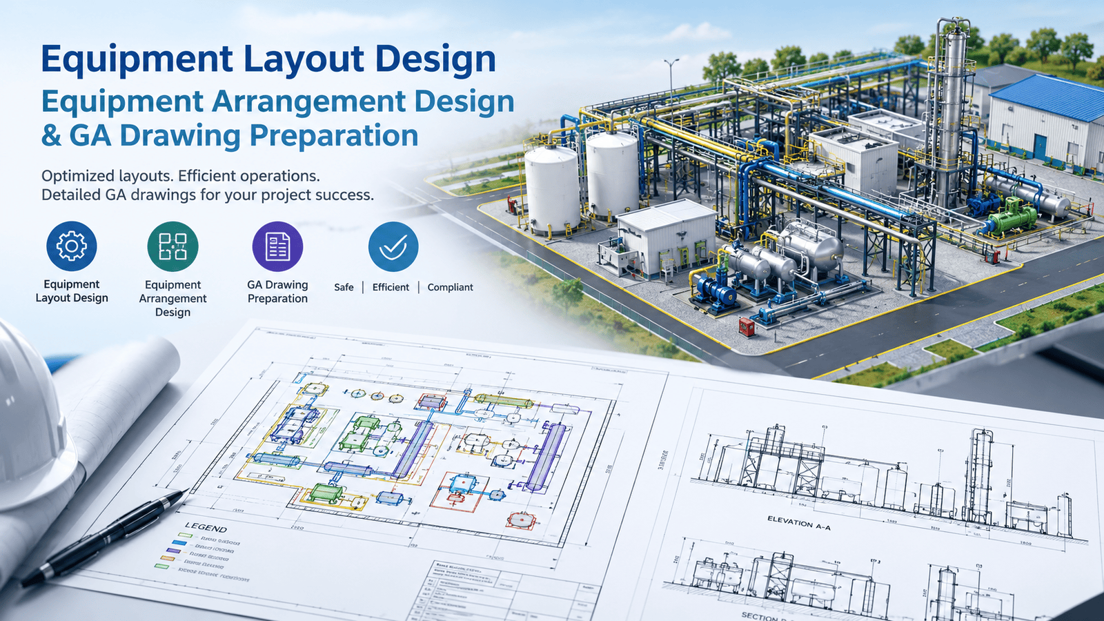
Industrial plants require more than correctly selected equipment. Pumps, compressors, heat exchangers, tanks, pressure vessels, utility systems, piping networks, and electrical installations must be arranged so that the facility can be constructed, operated, inspected, and maintained safely and efficiently.
This is where equipment layout design services and General Arrangement (GA) drawings become essential. A well-developed equipment layout helps engineering teams coordinate different disciplines, identify space constraints, plan maintenance access, and reduce avoidable changes during procurement and construction.
For EPC contractors and project owners, effective layout engineering is an important part of basic and detailed engineering. It connects process requirements with mechanical equipment, piping, civil and structural works, electrical systems, instrumentation, and construction planning.
AlgEnergy Engineering Consultancy Services provides multidisciplinary engineering consultancy and design support for power, renewable energy, industrial, and infrastructure projects. This article explains the scope of equipment layout engineering, the purpose of GA drawings, typical deliverables, and the factors that should be considered when appointing an engineering partner.
What Are Equipment Layout Design Services?
Equipment layout design services involve the systematic positioning of mechanical and process equipment within a plant or facility. The objective is to establish an arrangement that satisfies process requirements, operational needs, safety considerations, maintenance access, piping connections, structural constraints, and project-specific design criteria.
The layout may cover an entire industrial facility, an individual process unit, a power plant auxiliary system, a utility building, or a package supplied by an equipment vendor.
Typical equipment includes:
Pumps, compressors, blowers, and fans
Pressure vessels, storage tanks, and heat exchangers
Filters, separators, and treatment equipment
Cooling water and water-treatment systems
Fuel handling and utility equipment
Chemical dosing packages and skid-mounted systems
HVAC equipment and industrial ventilation systems
Power plant balance-of-plant equipment
The scope depends on the project phase and the information available. Early-stage engineering may establish equipment zones and preliminary arrangements, while detailed engineering develops dimensioned layouts, elevations, interfaces, access provisions, and coordinated drawings suitable for project execution.
Equipment Layout vs. General Arrangement Drawings
Equipment layout and GA drawings are closely related, but they do not always mean the same thing.
An equipment layout describes the relative position and orientation of equipment in a defined area. It considers access, operating requirements, piping routes, maintenance provisions, and interfaces with surrounding systems.
A General Arrangement drawing presents the overall physical arrangement of equipment, structures, access ways, and other relevant plant features. Depending on the project, it may include plans, elevations, sections, dimensions, coordinates, equipment tags, and reference levels.
A project may require several related drawings, including:
Overall plant plot plans
Equipment layout plans
Equipment arrangement drawings
General Arrangement plans and elevations
Building and equipment sections
Skid or package arrangement drawings
Equipment foundation interface drawings
Piping and mechanical coordination layouts
The exact drawing set should be defined in the engineering scope of work.
Why Is Equipment Layout Engineering Important?
An equipment arrangement can affect the cost, safety, maintainability, and construction sequence of a facility. A layout that appears acceptable on a preliminary plan may create problems when detailed piping, structural steel, access platforms, cable routes, or equipment-removal requirements are incorporated.
Professional layout engineering addresses these issues before they become expensive site modifications.
1. Efficient Use of Plant Space
Industrial land, process buildings, and equipment rooms often have fixed space limitations. Layout engineers must position equipment while preserving access routes, maintenance zones, operating clearances, and future expansion provisions where required.
Efficient space utilization should not mean placing equipment so closely together that operation, inspection, or replacement becomes difficult.
2. Safe Operation and Maintenance
Equipment must be accessible for routine operation, lubrication, inspection, calibration, and maintenance. The layout should account for operator access, emergency routes, lifting operations, removable components, and safe working areas.
Required clearances depend on equipment manufacturer recommendations, applicable regulations, project specifications, and the relevant engineering discipline.
3. Reduced Piping Complexity
Equipment positions influence piping length, routing, flexibility, support requirements, pressure losses, and access to valves and instruments. A coordinated layout can help reduce unnecessary routing complexity and improve constructability.
However, the shortest pipe route is not automatically the best solution. Piping stress, thermal movement, drainage, venting, equipment nozzle loads, and operating requirements must also be considered.
4. Better Multidisciplinary Coordination
Mechanical equipment interfaces with piping, civil and structural engineering, electrical power, instrumentation and control, HVAC, fire protection, and architectural systems.
A coordinated layout helps identify clashes and conflicting requirements early, reducing redesign during detailed engineering and construction.
5. Improved Construction Planning
Equipment delivery routes, crane access, installation sequence, lifting requirements, temporary openings, and maintenance-removal paths can affect construction feasibility.
Considering these requirements during design can help the EPC contractor plan installation and reduce the likelihood of costly rework.
Scope of Equipment Layout Design Services
The scope of work should reflect the project stage, equipment complexity, available inputs, and contractual requirements. A typical assignment may include the following activities.
1. Review of Engineering Inputs
The engineering team reviews available project documents to establish the basis for layout development.
Inputs may include:
Process flow diagrams and P&IDs
Equipment lists and preliminary datasheets
Vendor drawings and equipment outlines
Plot plans and building layouts
Project design basis and technical specifications
Civil and structural design information
Piping specifications and utility requirements
Electrical and instrumentation requirements
Applicable codes, regulations, and client standards
Missing or conflicting inputs should be recorded in a query or action register. Where information is preliminary, the layout should clearly identify assumptions that require confirmation.
2. Equipment Positioning and Orientation
Equipment is arranged according to process flow, system interfaces, operating requirements, access provisions, and available space.
The review considers suction and discharge connections, nozzle orientation, access to instruments, valve operation, equipment alignment, and interfaces with adjacent packages.
For rotating equipment, relevant considerations may include maintenance access, coupling and driver removal, alignment requirements, and manufacturer-recommended clearances.
For static equipment, the layout may need to accommodate manways, bundle or element withdrawal, inspection openings, lifting points, and access to platforms or ladders.
3. Maintenance and Equipment Removal Review
Equipment must be maintainable throughout its intended service life. Layout engineering should identify the space and facilities required for the removal or replacement of major components.
Examples include:
Pump and motor removal
Compressor maintenance
Heat exchanger bundle withdrawal
Filter element replacement
Vessel inspection and manway access
Valve removal and actuator maintenance
Crane, monorail, or lifting-beam requirements
Access for mobile maintenance equipment
The layout should demonstrate how critical maintenance activities can be performed. Where necessary, equipment-removal envelopes and lifting zones should be shown on the relevant drawings.
4. Piping and Utility Interface Coordination
Equipment layout development must be coordinated with piping engineering. The arrangement should support practical routing while maintaining access, drainage, venting, thermal flexibility, and equipment connection requirements.
The review may cover:
Suction and discharge nozzle accessibility
Pipe rack and corridor interfaces
Valve and instrument accessibility
Drain and vent locations
Pipe support and structural interfaces
Equipment nozzle load considerations
Thermal expansion and flexibility constraints
Utility connections and tie-in locations
Detailed piping stress analysis, support design, and hydraulic calculations may be separate work packages unless explicitly included in the contract.
5. Civil and Structural Coordination
Equipment layouts provide essential information for foundations, support structures, platforms, access stairs, and building openings.
Coordination may include equipment coordinates, baseplate dimensions, anchor bolt arrangements, foundation interfaces, operating and maintenance loads supplied by the relevant disciplines, and access requirements.
Foundation design and structural calculations should be undertaken by appropriately responsible engineers using verified design inputs.
6. Safety and Access Review
The layout should be checked against the project’s safety requirements and applicable regulations. Depending on the facility, the review may include escape routes, emergency access, hazardous-area interfaces, lifting zones, fire protection access, and separation requirements.
Requirements for hazardous installations, electrical equipment, pressure systems, chemical storage, and fire protection must be established using the applicable project standards and competent discipline reviews.
Key Deliverables in Equipment Layout and GA Engineering
Deliverables vary by project, but a typical equipment layout design package may include the following.
| Deliverable | Purpose |
|---|---|
| Equipment list review | Confirms equipment identification and key layout information |
| Preliminary equipment layout | Establishes initial equipment positioning and space requirements |
| Equipment layout plan | Shows equipment locations, orientation, and relevant dimensions |
| General Arrangement drawings | Presents overall arrangement in plan and, where needed, elevation or section |
| Equipment coordinates and elevations | Defines physical location and reference levels |
| Equipment access and maintenance review | Identifies operating and maintenance space requirements |
| Equipment-removal envelopes | Indicates the space required to remove selected components |
| Vendor drawing integration | Incorporates confirmed equipment dimensions and connection details |
| Piping interface layouts | Supports coordination of piping routes and equipment connections |
| Foundation interface information | Provides equipment location and interface details for civil and structural teams |
| 3D model review, where included | Helps identify spatial conflicts and coordination issues |
| Design review comments register | Records comments, responsibilities, and closure status |
| Final drawing package | Incorporates agreed comments and approved design information |
These are representative deliverables, not a universal contractual list. The final scope should define drawing formats, level of detail, revision stages, review cycles, model requirements, and approval responsibilities.
General Arrangement Drawings: What Should They Show?
GA drawings communicate the physical arrangement of a plant area or equipment package. Their content depends on the drawing purpose and design maturity.
A well-defined GA drawing may include:
Equipment tags and descriptions
Equipment outlines and orientations
Grid lines, coordinates, and dimensions
Floor levels and equipment elevations
Building columns, walls, and structural boundaries
Access platforms, ladders, and walkways
Maintenance and equipment-removal clearances
Major piping corridors and interface points
Relevant equipment nozzles or connection references
Foundation or baseplate interface information
Drawing notes, legends, and revision details
A preliminary GA drawing may use indicative equipment envelopes. A detailed GA drawing should use sufficiently verified dimensions and vendor information for its intended purpose.
The drawing status must be clear. A drawing issued for review should not be mistaken for an approved-for-construction document.
Equipment Layout Engineering for Different Industries
Thermal Power Plants and Balance of Plant Systems
Power projects contain many auxiliary systems whose physical arrangement influences plant operation and maintenance. These may include cooling water, compressed air, fuel oil, water treatment, chemical dosing, fire protection, wastewater treatment, and other mechanical utility systems.
Equipment layout engineering can support coordination of pumps, tanks, heat exchangers, filters, skids, pipe racks, and associated access provisions.
Power project requirements should be checked against applicable regulations, owner specifications, and relevant equipment and piping standards. For Indian power projects, the Central Electricity Authority provides technical standards and regulations relevant to electrical plants and power-sector engineering. See the official CEA standards and regulations.
Oil, Gas, and Process Industries
Process facilities may require careful arrangement of pressure vessels, pumps, compressors, heat exchangers, tanks, package equipment, and interconnected piping.
Layout reviews should consider the process design basis, hazardous-area requirements, access and escape provisions, equipment maintenance, lifting requirements, and relevant piping and pressure-system codes.
The applicable standards depend on the process, service, jurisdiction, and contractual design basis. ASME publishes codes and standards for areas including power piping and process-related engineering. Refer to the official ASME codes and standards directory.
Water and Wastewater Treatment Plants
Water treatment facilities may include raw-water pumps, chemical dosing systems, filters, clarifiers, tanks, blowers, sludge-handling equipment, and utility packages.
The layout must accommodate process flow, access to instruments and valves, chemical handling, drainage, equipment maintenance, and interfaces with civil structures and pipelines.
Renewable Energy and Battery Storage Projects
Solar, wind, and battery energy storage projects also require coordinated layouts for auxiliary equipment, electrical and mechanical interfaces, HVAC, fire protection, and utility systems.
For battery energy storage systems, equipment arrangement should be based on the selected technology, vendor instructions, applicable fire and electrical requirements, site conditions, and project-specific safety studies. Separation distances and access provisions should never be assumed from generic layouts alone.
Codes, Standards, and Design Criteria
Equipment layout engineering does not rely on a single universal code. The applicable requirements depend on the industry, equipment, project location, owner specifications, and the scope of engineering responsibility.
A project design basis may reference:
Applicable national regulations and statutory requirements
Client engineering standards and project specifications
Equipment manufacturer installation and maintenance instructions
Relevant ASME codes for equipment or piping within their scope
Applicable ISO standards for the relevant subject
Fire protection and electrical requirements applicable to the facility
Project-specific safety studies and risk assessments
For example, ASME B31.1 addresses power piping within its defined scope; it is not a general-purpose code for every plant layout. The selected code and edition must be confirmed against the project requirements. Refer to the official ASME Power Piping information.
ISO standards can be researched through the official ISO standards catalogue.
Important: A reference to a standard does not automatically mean that every provision applies to every project. The responsible engineering team should establish the applicable codes, editions, jurisdictional requirements, and client-specific criteria during project initiation.
Common Equipment Layout Problems and How to Prevent Them
Incomplete Vendor Information
Preliminary equipment dimensions may change when the selected vendor submits certified drawings.
Recommended approach: Maintain a vendor-document register, identify preliminary dimensions, and review layouts against the latest approved equipment information before releasing dependent drawings.
Insufficient Maintenance Space
Equipment may fit within a building but still be difficult to maintain because motors, bundles, filters, or other components cannot be removed.
Recommended approach: Review maintenance activities and removal envelopes before finalizing equipment positions.
Piping and Structural Clashes
Piping routes may conflict with beams, platforms, cable trays, ducts, or access ways.
Recommended approach: Coordinate layouts across disciplines and use 3D model reviews where the project scope and available model maturity justify them.
Poor Access to Valves and Instruments
Equipment connections may be physically possible but difficult to operate, inspect, or reach safely.
Recommended approach: Include operations and maintenance requirements in layout reviews, and verify access against project-specific criteria.
Late Changes During Construction
A change to one equipment item can affect piping, foundations, steelwork, electrical interfaces, and procurement.
Recommended approach: Use a defined review and change-control process, track assumptions, and communicate design revisions to affected disciplines.
Why Outsource Equipment Layout Design Services?
EPC contractors and engineering consultancies may outsource equipment layout work when project workloads increase, specialist resources are limited, or additional engineering capacity is required.
Engineering design outsourcing can provide access to additional mechanical engineering resources while allowing the main project team to retain control over design criteria, interfaces, and approvals.
Potential benefits include:
Additional design capacity during peak workloads
Support for basic and detailed engineering packages
Assistance with equipment arrangement and GA drawings
Coordination support across mechanical and piping disciplines
Flexible resource deployment for defined work packages
Reduced pressure on in-house teams during project deadlines
Successful outsourcing requires a clear scope, reliable inputs, agreed software and drawing standards, document control, communication procedures, and defined checking and approval responsibilities.
Outsourcing should not be treated as a substitute for project-specific technical review. Final responsibility must follow the contract, applicable regulations, and the agreed engineering quality system.
How to Select an Equipment Layout Engineering Consultant
Before appointing a consultant, EPC contractors and project owners should assess several factors.
Relevant project experience: Confirm experience with the type of facility, equipment, and project phase involved.
Mechanical engineering capability: Check whether the team understands equipment datasheets, vendor drawings, piping interfaces, maintenance requirements, and mechanical utilities.
Multidisciplinary coordination: Establish how the consultant will coordinate with piping, civil and structural, electrical, instrumentation, HVAC, and process teams.
Deliverable clarity: Agree on drawing lists, formats, review stages, model requirements, and final issue status.
Quality control: Confirm checking procedures, revision control, comment resolution, and document traceability.
Communication and delivery: Define milestones, technical query procedures, reporting, and responsibilities for client or vendor inputs.
Scope boundaries: Specify whether 3D modelling, site surveys, foundation design, detailed piping, stress analysis, construction support, and as-built updates are included or excluded.
AlgEnergy Equipment Layout and Mechanical Engineering Support
AlgEnergy Engineering Consultancy Services supports multidisciplinary engineering requirements across power, renewable energy, industrial, and infrastructure projects.
Depending on the project scope and agreed deliverables, equipment layout assignments may be coordinated with related services such as basic and detailed engineering, piping and mechanical engineering, technical and vendor coordination, and plant engineering support.
Potential work packages include:
Equipment arrangement and layout development
GA drawing preparation and review
Mechanical equipment interface coordination
Maintenance access and equipment-removal reviews
Piping and utility interface coordination
Vendor drawing review and incorporation
Engineering design support for EPC contractors
Drawing review, comment resolution, and revision control
The final scope, engineering deliverables, schedule, and resource plan should be agreed after reviewing the project documents and required level of design maturity.
How to Start an Equipment Layout Engineering Assignment
To obtain a useful proposal, provide the engineering consultant with the following information where available:
Project type, location, and current engineering phase.
Description of the plant area or equipment package.
Equipment list and preliminary or approved datasheets.
Available plot plans, P&IDs, vendor drawings, and building layouts.
Applicable design standards and client specifications.
Required drawings, models, software, and file formats.
Required schedule, milestones, and review cycles.
Scope boundaries and the expected role of the consultant.
If some inputs are unavailable, identify them clearly so that the consultant can state assumptions, exclusions, and information required before starting.
Frequently Asked Questions
1. What are equipment layout design services?
They cover the planning and engineering of equipment positions, orientations, access, maintenance space, and interfaces within an industrial plant or facility.
2. What is the purpose of a GA drawing?
A General Arrangement drawing communicates the overall physical arrangement of equipment and relevant structures, dimensions, levels, access provisions, and interfaces needed for coordination and project execution.
3. What is the difference between an equipment layout and a GA drawing?
An equipment layout focuses on equipment positioning and relationships. A GA drawing presents the arrangement in a defined drawing format, often with dimensions, elevations, sections, and interface information. The terms may overlap depending on the project.
4. Which inputs are required for equipment layout engineering?
Common inputs include equipment lists, datasheets, P&IDs, vendor drawings, plot plans, building information, piping requirements, client standards, and maintenance criteria.
5. Can equipment layouts be developed before vendor selection?
Yes. Preliminary layouts can be developed using estimated dimensions and defined assumptions. They should be updated when verified vendor drawings become available.
6. Does equipment layout design include piping stress analysis?
Not automatically. Piping layout coordination and piping stress analysis are related but distinct activities. The proposal should clearly state whether stress analysis, support design, and associated calculations are included.
7. Can equipment layout engineering be outsourced to India?
Yes. EPC contractors and engineering companies can outsource defined engineering work packages to Indian engineering service providers. The parties should agree on technical standards, software, deliverables, checking procedures, communication, and design responsibility.
8. How can I request a proposal from AlgEnergy?
Share your project description, available engineering inputs, expected deliverables, required completion date, and contact details through AlgEnergy's official website. The scope can then be reviewed to establish the information required for a proposal.
Request Equipment Layout Engineering
Are you planning a new industrial facility, expanding an existing plant, or supporting an EPC project that requires equipment arrangement and GA drawings?
AlgEnergy Engineering Consultancy Services welcomes enquiries from EPC contractors, industrial project owners, engineering consultancies, and international project teams seeking mechanical engineering and layout design support.
Discuss your equipment layout engineering requirements. Share the project type, engineering phase, available drawings, deliverables, and schedule so the required scope can be assessed.
Visit the AlgEnergy Engineering Consultancy Services website to make an enquiry.
Engineering note: Final layouts and GA drawings should be reviewed and approved by the responsible project disciplines in accordance with applicable regulations, project specifications, verified vendor data, and contractual design responsibilities.