3D Piping Design Services: Benefits, Workflow, Deliverables & Applications
Introduction: Why 3D Piping Design Services Matter for Modern EPC Projects
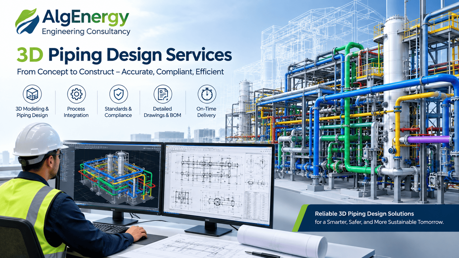
Modern industrial facilities require accurate engineering, efficient space utilization, coordinated equipment arrangements and reliable construction documentation. Whether a project involves a thermal power plant, renewable energy facility, process plant, water treatment system, chemical manufacturing unit or industrial utility network, piping is one of the essential components connecting equipment, utilities and operating systems.
Poorly coordinated piping layouts can lead to equipment access problems, routing conflicts, unnecessary bends, difficult maintenance, material wastage, construction rework and schedule delays. These challenges become more significant when several engineering disciplines are working simultaneously on a large project.
3D piping design services help address these challenges by creating a coordinated three-dimensional representation of piping systems, equipment, structures and other plant components before physical installation begins.
Instead of relying exclusively on individual two-dimensional drawings, engineering teams can use a 3D model to visualize piping routes, inspect equipment interfaces, review maintenance clearances, identify potential clashes and extract project-specific engineering deliverables.
For engineering, procurement and construction (EPC) contractors, 3D piping design is not simply a visualization activity. It is an important part of the engineering workflow that connects design development, multidisciplinary coordination, material estimation, procurement, fabrication and construction.
A well-developed piping model can support:
Equipment and piping layout optimization.
Pipe routing and elevation coordination.
Identification of geometric clashes.
Review of accessibility and maintenance requirements.
Generation of piping isometric drawings.
Material take-off (MTO) and bill of quantities support.
Coordination between piping, civil, structural, electrical and instrumentation teams.
Construction planning and design review.
Engineering outsourcing and resource optimization.
AlgEnergy Engineering Consultancy Services provides multidisciplinary engineering support for power, renewable energy, industrial infrastructure, utilities and related projects. Its broader service portfolio includes piping and mechanical engineering, detailed engineering, technical coordination and project execution support. Explore the AlgEnergy engineering consultancy services to understand how piping design can fit within a wider project engineering scope.
This guide explains the meaning of 3D piping design, its benefits, engineering workflow, deliverables, applications, software considerations, outsourcing models, quality requirements and the factors EPC contractors should evaluate when selecting a piping design partner.
It also explains how project owners and engineering companies in India and international markets can structure a piping design enquiry to obtain a technically appropriate proposal.
What Are 3D Piping Design Services?
3D piping design services involve developing a digital three-dimensional model of piping systems and associated plant components using engineering design software.
The model represents the spatial arrangement of pipes, fittings, valves, flanges, supports, equipment connections and other relevant components. Depending on the project scope, it may also include structural steel, access platforms, cable trays, instrumentation, HVAC systems, equipment foundations and other discipline interfaces.
The purpose is to create a coordinated representation of the facility that supports engineering review and downstream project activities.
Understanding 3D piping modelling
In a conventional 2D workflow, engineers review plan drawings, elevations, sections, piping layouts and individual isometric drawings to understand the proposed system.
Although these documents remain essential, understanding complicated routing from multiple drawings can be difficult, particularly in congested plant areas.
A 3D piping model brings these spatial relationships into a common digital environment. Engineers can inspect the model from different viewpoints, examine equipment connections, assess pipe elevations and identify potential conflicts between components.
For example, consider a cooling water system serving several pumps and heat exchangers in a power plant.
The piping engineer must establish suitable pipe routes while considering:
Pump suction and discharge connections.
Pipe diameters and required flow capacity.
Valve positions and accessibility.
Equipment maintenance requirements.
Structural steel and building clearances.
Pipe support locations.
Instrument connections.
Drainage and venting requirements.
Interference with cable trays and other services.
Installation and fabrication constraints.
A coordinated 3D piping model helps the engineering team review these requirements together rather than treating each route as an isolated drawing.
What is included in a 3D piping design package?
The scope depends on the project stage, available engineering inputs and contractual requirements.
A typical package may include:
Review of design inputs and engineering documents.
Piping design basis and routing criteria.
Equipment and piping model development.
Piping layout and routing.
Model coordination and clash detection.
Piping general arrangement drawings.
Piping isometric drawings.
Pipe support location information and associated drawings, where included.
Material take-off and line-based material summaries.
Model review reports.
Design comment resolution.
As-built model and drawing updates, where included in the scope.
Not every project requires all these deliverables. The scope should identify which documents are included, their level of detail, applicable software formats, review stages and acceptance requirements.
3D piping design versus 3D plant modelling
The terms are related but not identical.
3D piping design focuses on the arrangement and routing of piping systems, including pipes, fittings, valves, connections and related components.
3D plant modelling covers a wider portion of the facility. It may include equipment, structural steel, platforms, buildings, piping, cable trays, HVAC and other plant systems.
For a large industrial or power project, the two activities are usually coordinated. The plant model establishes the wider physical environment, while the piping model develops the detailed routes and connections within that environment.
This distinction is important when preparing an EPC tender or outsourcing scope. A contractor requiring piping routing alone may not need a complete plant model, whereas a project requiring multidisciplinary clash detection may need broader modelling coverage.
Why EPC Contractors Need Professional 3D Piping Design Services
EPC contractors are responsible for integrating engineering, procurement and construction activities within defined technical, commercial and schedule requirements.
Piping design influences several of these activities simultaneously. A routing decision can affect pipe quantities, support arrangements, fabrication requirements, access for equipment maintenance and the sequence of installation.
Professional 3D piping design services can help EPC contractors manage these interfaces more systematically.
1. Improved piping layout accuracy
A three-dimensional model allows engineers to examine pipe routes in relation to actual equipment and structural arrangements.
This is particularly useful where multiple lines occupy a limited space or where piping must pass through several elevations.
Model-based review helps the team examine:
Pipe-to-equipment interfaces.
Vertical and horizontal routing.
Pipe spacing and accessibility.
Connection orientations.
Intersections with structural members.
Routing through designated corridors.
Potential restrictions near access platforms.
Installation clearances around equipment.
The model does not replace engineering calculations or design checks. Instead, it provides a spatial framework in which engineering decisions can be reviewed more effectively.
2. Early identification of design clashes
A clash occurs when two modelled components occupy overlapping or incompatible space, or when their proximity violates an applicable clearance requirement.
For example, a cooling water pipe may intersect a structural beam, or a cable tray may conflict with a proposed pipe route.
Clash detection can identify many of these issues before fabrication or installation. This allows engineers to assess alternatives while the design is still being developed.
Typical coordination issues include:
Pipe-to-pipe interference.
Pipe-to-structure clashes.
Pipe-to-equipment conflicts.
Piping and cable tray interference.
Access platform and valve conflicts.
Equipment maintenance clearance problems.
Routing conflicts at congested intersections.
Not all clashes have the same importance. Some are direct geometric collisions, while others are clearance violations or constructability concerns. The model review process should classify issues and assign responsibility for resolving them.
3. Better multidisciplinary coordination
Industrial facilities typically involve several engineering teams working in parallel.
The piping discipline must coordinate with mechanical equipment, civil and structural engineering, electrical engineering, instrumentation and control, HVAC, fire protection and process engineering.
A shared or federated 3D model provides a common reference for these disciplines.
For example, the piping team may propose a route through a corridor that the electrical team has allocated for cable trays. A coordinated model review can expose the conflict and help the teams agree on a practical arrangement.
Effective coordination depends on more than software. It requires clear modelling boundaries, consistent coordinate systems, document revisions, clash review procedures and timely resolution of technical comments.
4. Improved construction planning
Construction teams need to understand how piping components will be installed, connected, supported and accessed.
A coordinated model can assist with installation sequencing, congested-area reviews and identification of locations where access for welding, bolting, lifting or inspection may be restricted.
For example, large-bore piping installed above equipment may require a different installation sequence from smaller utility lines routed around existing services.
Model reviews can help identify potential access problems before site work begins.
Actual construction planning must also consider lifting studies, temporary works, site conditions, safety requirements and the construction contractor's approved methodology.
5. Better material estimation
Accurate model geometry and properly configured component data can support piping material take-off.
Depending on the software and modelling standards, quantities may be extracted for:
Straight pipe lengths.
Elbows and bends.
Tees and reducers.
Flanges.
Valves.
Gaskets and bolting.
Specialty components.
Pipe supports, where modelled.
Other piping materials defined in the project specification.
The reliability of these quantities depends on model completeness, component catalogues, specifications, modelling rules and revision control.
A 3D model should not be treated as a fully verified procurement quantity source unless the required checks and exclusions have been defined.
6. Reduced design rework
Design rework may arise when piping routes are developed without sufficient consideration of equipment interfaces, structural arrangements, installation requirements or other disciplines.
A structured 3D review process can identify some of these issues earlier.
The commercial benefit depends on the quality of the design inputs, the number of review cycles, the accuracy of the model and the extent to which identified issues are resolved before construction.
For EPC contractors, the objective is not merely to produce a visually attractive model. It is to improve coordination and deliver engineering documents that support project execution.
Key Benefits of 3D Piping Design and Layout Engineering
The value of 3D piping design becomes clearer when its technical advantages are connected to project delivery requirements.
Design visualization and spatial understanding
A three-dimensional representation helps engineers, project managers, clients and construction personnel understand the proposed piping arrangement.
This is especially useful for complex equipment rooms, utility corridors, pipe racks, pump houses, process units and facilities with multiple elevation levels.
During design reviews, the team can examine the arrangement from different viewpoints and identify areas requiring further engineering attention.
Improved space utilization
Industrial space is expensive to develop, construct and maintain. Uncoordinated piping can occupy unnecessary space, obstruct access routes or create conflicts with equipment and structures.
Piping layout design should therefore balance compact routing with engineering requirements, safety, maintenance and constructability.
A well-coordinated model can help engineers compare routing alternatives and use available space more effectively without compromising required clearances or operating needs.
Consistent drawing development
Where the selected software supports drawing extraction, the approved 3D model can provide a common geometric basis for piping layouts, isometrics and other project drawings.
This helps reduce inconsistencies between documents, provided that model changes are properly managed and the drawings are regenerated or updated through the controlled project process.
The model should remain aligned with the latest approved engineering inputs and piping specifications.
Improved vendor and equipment interface management
Piping design depends on accurate equipment connection details, nozzle orientations, dimensions and vendor-approved drawings.
Changes to a pump, heat exchanger, tank or packaged equipment skid may affect the connected piping system.
A structured model review process helps identify affected routes and interface points when equipment dimensions or connection details change.
More informed engineering decisions
A model can support comparisons between alternative routing arrangements.
Engineers may evaluate factors such as route length, fitting requirements, accessibility, support locations, congestion and installation complexity.
These comparisons help inform decisions, but the final selection must also account for process hydraulics, stress requirements, operating conditions, safety, cost and applicable project standards.
Better support for remote engineering teams
Engineering outsourcing often involves clients, designers, vendors and project sites in different locations.
A controlled 3D model, documented review comments and agreed revision procedures can make remote design coordination more practical.
This is particularly relevant when international EPC contractors outsource defined engineering packages to specialist teams in India or other engineering service centres.
Potential cost and schedule benefits
3D piping design may contribute to reduced rework, better quantity control and improved coordination. However, the actual benefit depends on the project and should not be expressed as a guaranteed percentage without supporting evidence.
Project teams can assess value using indicators such as:
Number of significant clashes identified before construction.
Number of design comments resolved per review cycle.
Drawing revision frequency.
Quantity discrepancies between model and procurement documents.
Engineering hours spent on rework.
Construction queries attributable to design coordination.
Percentage of deliverables approved on schedule.
Tracking these indicators helps establish whether the modelling workflow is improving project performance.
3D Piping Design Workflow: From Engineering Inputs to Construction Deliverables
A structured workflow is essential to achieve reliable 3D piping modelling results. The exact sequence depends on project complexity, software, client procedures and the engineering stage.
For most industrial and EPC projects, the workflow can be organized into the following stages.
Stage 1: Project requirement review
The first step is to establish the scope of work and understand what the client expects from the piping design package.
The engineering team should review:
Project scope and battery limits.
Process and utility requirements.
Available PFDs and P&IDs.
Equipment lists and data sheets.
Equipment vendor drawings.
Plot plans and general arrangements.
Piping material specifications.
Line lists and operating conditions.
Applicable codes and standards.
Required drawing and model formats.
Project schedule and review milestones.
The team should also identify missing information, unresolved technical queries and assumptions that could affect the model.
A clear scope definition prevents misunderstandings about whether the assignment includes only piping routing or also support design, stress analysis, fabrication drawings, MTO, as-built updates and other deliverables.
Stage 2: Establish the piping design basis
The piping design basis defines the technical rules governing the modelling and layout process.
Depending on the project, it may establish:
Units of measurement.
Plant coordinate system and elevations.
Piping classes and material specifications.
Line numbering conventions.
Pipe routing criteria.
Minimum access and maintenance clearances.
Equipment connection requirements.
Valve accessibility requirements.
Drain and vent philosophy.
Insulation and tracing requirements.
Pipe support design interfaces.
Model naming and file conventions.
Drawing standards and revision rules.
The design basis should reflect the project's actual engineering requirements rather than relying on generic assumptions.
Stage 3: Review PFDs, P&IDs and line lists
Process and utility documents establish which systems need to be modelled and how they connect.
The piping team reviews P&IDs to identify line numbers, sizes, valves, fittings, instruments, equipment connections and relevant system arrangements.
Line lists provide additional information, which may include line size, fluid service, design pressure, design temperature, material specification, insulation and other project-specific parameters.
Discrepancies between the P&IDs, line lists and equipment information should be resolved through the project's technical query process.
The modelling team must not independently alter process requirements merely to simplify routing.
Stage 4: Develop the equipment and structural reference model
Piping routing requires an accurate representation of the physical environment.
Depending on the scope, this may involve importing or modelling:
Pumps and compressors.
Tanks and pressure vessels.
Heat exchangers.
Filters and strainers.
Package equipment.
Structural steel.
Equipment foundations.
Platforms and access structures.
Buildings and major architectural elements.
Cable trays and other services.
Existing facilities for retrofit projects.
Equipment connection points should be established using approved vendor drawings or verified project data.
If dimensions are preliminary, the model should identify them as such so that the design team can revisit affected areas when final information becomes available.
Stage 5: Develop piping routes
Piping routing is the process of establishing the path between system connection points while meeting engineering, operating and construction requirements.
The route should account for pipe diameter, component geometry, equipment orientation, required elevations, access, supports and other relevant constraints.
For a pump suction line, for example, the engineer may need to consider the equipment manufacturer's recommendations, hydraulic requirements, line arrangement and applicable project criteria.
For a large utility header, the routing exercise may also consider structural supports, branch connections, thermal movement, isolation points and maintenance access.
The 3D model helps visualize the route, but engineering calculations and discipline-specific checks remain necessary.
Stage 6: Model valves, fittings and specialty components
Once the major routes are established, the team develops the detailed piping geometry.
This can include elbows, tees, reducers, flanges, valves, strainers, expansion joints, specialty items, drains, vents and instrumentation connections.
Components should use the appropriate project catalogue and specification wherever available.
Incorrect component selection or incomplete data can affect both the geometry and the extracted material quantities.
Stage 7: Coordinate pipe supports and interfaces
Pipes require appropriate support arrangements based on their size, material, contents, operating temperature, weight and other loading conditions.
Support locations should be coordinated with structural steel, equipment connections and access requirements.
Where pipe stress analysis is required, the routing model must be coordinated with the stress analysis model and the resulting support and flexibility recommendations.
A routing designer should not assume that geometric clearance alone establishes the structural adequacy of a pipe support or the flexibility of a piping system.
The project scope should clearly define responsibility for support design, stress analysis, structural verification and final engineering approval.
Stage 8: Conduct multidisciplinary clash detection
Clash detection checks the model for geometric conflicts and selected clearance violations.
The model may be reviewed against structural, electrical, instrumentation, HVAC and other discipline models.
The clash review should establish:
The type and severity of the issue.
The affected components.
The responsible discipline.
The proposed resolution.
The action owner.
The target closure date.
The verification status.
Clash reports should distinguish between actionable design issues, acceptable conditions, duplicate findings and issues requiring additional engineering judgment.
The goal is to resolve important coordination problems, not merely to achieve a zero-clash report by ignoring difficult interfaces.
Stage 9: Review constructability and maintainability
A piping route may be geometrically possible but difficult to install or maintain.
The design review should therefore consider access for welding, bolting, valve operation, equipment removal, inspection and future maintenance.
Other relevant questions include:
Can the pipe spool be fabricated and transported?
Is there sufficient space for installation equipment?
Can valves be operated safely?
Can instruments be accessed for inspection?
Are drains and vents accessible?
Can equipment be removed without dismantling excessive piping?
Are required lifting and maintenance clearances preserved?
These reviews should involve the relevant engineering, construction and operations stakeholders.
Stage 10: Generate piping isometric drawings
Piping isometrics represent selected piping lines in a dimensioned drawing format suitable for engineering review, fabrication and installation, according to the project requirements.
They may include:
Line identification.
Pipe sizes and specifications.
Dimensions and elevations.
Fittings and valves.
Weld locations and weld identification, where required.
Component item numbers.
Material lists.
Tie-in details.
Fabrication and installation notes.
The level of detail varies by project and by whether the drawing is intended for design review, fabrication or construction.
Isometric drawings must be checked for dimensional accuracy, line continuity, component completeness and consistency with the approved model and project specifications.
Stage 11: Extract material take-offs
Where the model is configured with suitable component data, the engineering team can generate material quantities for procurement and estimation.
Typical outputs include pipe lengths, fittings, flanges, valves and other specified components.
Before quantities are issued for procurement, the team should confirm:
Model completeness.
Correct piping specifications.
Component catalogue accuracy.
Inclusion and exclusion rules.
Treatment of temporary items.
Treatment of field-fit components.
Insulation and coating requirements.
Revision status and quantity reconciliation.
Material take-off is only as reliable as the underlying model and the defined extraction procedure.
Stage 12: Engineering review, approval and revision control
The final stage involves controlled review and issue of the required engineering deliverables.
The model and associated drawings should follow the client's document control procedure, revision numbering system and approval workflow.
Comments should be recorded, assigned and closed in a traceable manner.
Where the project requires construction issue documents, the relevant deliverables must be reviewed and approved through the designated project process before being released for use.
This stage provides the link between digital modelling and the controlled engineering documents used by procurement, fabrication and construction teams.
Essential Deliverables in a 3D Piping Design Package
The deliverables depend on whether the client requires concept modelling, basic engineering, detailed engineering, fabrication documentation or construction support.
The following list describes common outputs that may be included in a professional piping design scope.
1. Piping layout drawings
Piping layout drawings communicate the arrangement of piping systems within a plant area.
They may show:
Pipe routing.
Equipment locations.
Pipe rack arrangements.
Line identification.
Major dimensions.
Elevations.
Access routes.
Equipment connections.
Structural interfaces.
These drawings provide a practical reference for engineering reviews and coordination.
2. 3D piping model
The three-dimensional model represents the piping geometry and associated components within the agreed modelling boundary.
The client should specify the native authoring format, any required neutral exchange formats, model segmentation, file naming and handover requirements.
The model's level of detail should match its intended purpose. A concept model, a coordination model and a fabrication-oriented model have different requirements.
3. Piping isometric drawings
Isometric drawings provide dimensioned representations of individual piping lines or spools, according to the project requirements.
They support engineering verification, fabrication planning and installation.
The scope should clarify whether isometrics include material lists, weld information, spool identification, support details and construction notes.
4. General arrangement drawings
General arrangement drawings show the broader arrangement of equipment, piping and associated structures.
They may include plans, elevations and sections that communicate dimensions, orientations, clearances and interface information.
5. Clash detection and model review reports
Clash reports document identified conflicts between model components.
A useful report includes the issue description, affected components, location, responsible discipline, severity, proposed action and closure status.
The report should support a defined review process rather than simply listing unverified model intersections.
6. Material take-off reports
Material take-off reports summarize model-derived quantities for piping components and other items included in the extraction scope.
The report may be grouped by line number, piping class, size, component type or procurement package.
Project-specific exclusions and the model revision used for the extraction should be documented.
7. Pipe support drawings and schedules
Where included in the scope, support deliverables may identify support locations, support types, relevant dimensions and coordination information.
Detailed structural design and pipe stress verification may require separate engineering deliverables and approval responsibilities.
8. Design review and interface registers
Registers help track technical queries, design comments, interface issues and outstanding information.
These documents are particularly valuable on projects involving multiple contractors, international engineering teams and staggered design packages.
9. As-built drawings and model updates
For brownfield projects or completed installations, the client may require as-built updates reflecting verified site conditions.
The scope should establish the source of field information, survey accuracy, site verification responsibilities and approval process.
An as-built model should not be represented as field-verified unless the required verification has actually been performed.
Software and Technology Used for 3D Piping Design
Software selection should follow the project's technical requirements rather than brand preference alone.
Different tools provide different capabilities for piping modelling, plant design, clash detection, drawing production, collaboration and stress analysis.
Plant 3D design software
Autodesk Plant 3D is one example of software used for plant layout and piping design. Depending on the configuration and project requirements, plant design tools can support piping modelling, equipment arrangement, orthographic drawings, isometrics and related documentation.
Official reference: Autodesk Plant 3D.
AVEVA and other plant design platforms
AVEVA provides engineering and industrial software used in plant design and related engineering workflows. The appropriate product and data-exchange method depend on the client environment and project configuration.
Official reference: AVEVA.
Navisworks and model coordination
Model coordination tools can be used to review models from multiple disciplines and investigate potential geometric conflicts.
For example, Navisworks is commonly associated with model aggregation, review and clash workflows.
Official reference: Autodesk Navisworks.
Piping stress analysis software
Geometric routing and piping stress analysis are related but distinct engineering activities.
Stress analysis tools can be used to evaluate piping systems under defined load cases, including applicable operating, thermal, weight, pressure, seismic and other project-specific loads.
CAESAR II is an example of software used for piping stress analysis.
Official reference: Hexagon.
The project team should establish how the piping model, stress analysis model, support recommendations and final routing revisions will be coordinated.
Interoperability and data exchange
International EPC projects may involve several software platforms and contractors.
Before starting work, the parties should agree on:
Native model formats.
Neutral exchange formats, where required.
Coordinate systems and units.
Model segmentation and reference models.
Revision and change management.
Component property requirements.
Drawing extraction standards.
Ownership and handover of model data.
Software compatibility should be verified using a representative test file before large-scale modelling begins.
Applications of 3D Piping Design Services Across Industries
Piping design requirements vary significantly by industry. Fluid properties, pressure, temperature, operating conditions, applicable codes, plant arrangement and maintenance requirements all influence the final layout.
AlgEnergy's multidisciplinary engineering portfolio covers power, renewable energy, industrial infrastructure, water systems and related engineering applications.
1. Thermal power plants
Thermal power plants contain extensive piping networks serving steam, condensate, cooling water, fuel, compressed air, fire protection, water treatment and auxiliary systems.
3D piping design can support equipment arrangement, pipe routing, coordination with structural steel and electrical services, and preparation of engineering drawings.
High-temperature and high-pressure systems require particular attention to piping material specifications, thermal expansion, stress analysis, support design and applicable power plant engineering requirements.
2. Solar power and battery energy storage projects
Solar PV and battery energy storage system projects can include piping for cooling systems, fire protection, water treatment, drainage and associated utilities, depending on the technology and facility configuration.
Piping modelling may be coordinated with electrical infrastructure, equipment pads, buildings, cable trays and service access areas.
For projects that combine solar generation with battery storage, the design team must also coordinate the relevant mechanical, electrical, civil and safety interfaces.
Learn more about AlgEnergy's broader capabilities through its engineering services.
3. Water treatment plants
Water treatment facilities use piping for raw water, treated water, chemical dosing, backwash, sludge, drainage and utility services.
A 3D model can help coordinate pumps, tanks, filters, membranes, valves, manifolds, pipe racks and equipment connections.
The design should consider hydraulic requirements, access to valves and instruments, drainage, maintenance, materials compatibility and applicable process requirements.
4. Effluent and sewage treatment plants
Effluent treatment plants and sewage treatment plants often have congested equipment areas, multiple process stages and extensive utility networks.
3D piping modelling can support coordination around aeration systems, pumps, tanks, filters, chemical dosing equipment, sludge handling systems and associated utilities.
For additional information about related engineering scope, see AlgEnergy's WTP, ETP and STP engineering design guide.
5. Chemical and process plants
Chemical plants may contain process lines with demanding requirements for pressure, temperature, corrosion resistance, fluid compatibility and operational safety.
Piping design must follow approved process documents, piping specifications, hazardous-area requirements where relevant, and applicable engineering codes.
Three-dimensional modelling supports routing and interface review, but process safety, materials selection, relief system design and other specialist engineering requirements must be addressed by the responsible disciplines.
6. Oil and gas facilities
Oil and gas facilities may include production equipment, storage systems, utility networks, pump stations, process units, metering systems and associated infrastructure.
3D piping design can support congested layouts and coordination between piping, equipment, structures and instrumentation.
The design must reflect the project's applicable requirements for pressure systems, materials, inspection, safety and operational access.
7. LNG and gas infrastructure
LNG and gas facilities involve piping systems that may operate under demanding pressure and temperature conditions.
Design considerations can include material selection, thermal movement, equipment interfaces, hazardous-area requirements, isolation, emergency access and system-specific safety provisions.
Cryogenic services require particular care because material behaviour and thermal contraction can influence the design.
8. Industrial manufacturing facilities
Manufacturing facilities often require compressed air, cooling water, process utilities, drainage, fire protection and other service networks.
A coordinated model can help manage piping routes around production equipment, electrical installations, structural members and maintenance access areas.
The design approach should account for operational continuity, future expansion and the practical requirements of installation in an operating facility.
9. Retrofit and brownfield projects
Existing facilities present additional challenges because original drawings may be incomplete, outdated or inconsistent with actual site conditions.
Brownfield 3D piping design may require site surveys, laser scanning or verified measurements, existing equipment modelling and coordination with ongoing operations.
Before designing modifications, the project team should confirm which dimensions and interface details have been field-verified.
10. Building utilities and infrastructure
Large commercial, institutional and infrastructure facilities may use 3D modelling to coordinate water supply, drainage, fire protection, HVAC-related services and other mechanical utilities.
Depending on the project, the modelling scope may be classified as building services coordination, MEP modelling or industrial piping design.
The terminology used in the proposal should reflect the actual service being delivered.
Piping Design Outsourcing: Why EPC Contractors Use External Engineering Teams
Piping design outsourcing allows EPC contractors, plant owners and engineering consultants to assign defined design activities to an external engineering service provider.
The objective may be to increase engineering capacity, address a temporary workload peak, obtain specialist skills or complete a specific package without expanding permanent staffing.
Access to additional engineering resources
Large projects may require more piping designers and modellers than an in-house team can provide at a particular stage.
An outsourcing arrangement can provide additional resources for model development, drawing production, isometric generation, MTO preparation or coordination support.
The provider should demonstrate that the proposed resources have relevant experience with the project's software, modelling standards and deliverable requirements.
Flexible project staffing
Engineering workloads fluctuate during design development, vendor data integration, model reviews and construction issue.
A defined outsourcing package can help the contractor scale capacity according to the approved schedule.
However, resource flexibility should not replace proper planning. Mobilization time, onboarding, model access, design inputs and review cycles can all affect actual productivity.
Support for international EPC projects
International EPC contractors may outsource piping design work to specialist teams in India to complement their internal engineering resources.
A successful arrangement requires clear communication, defined technical responsibility, secure document exchange, suitable time-zone overlap and controlled revisions.
The client should evaluate the provider based on engineering competence, quality processes, delivery capability and coordination discipline rather than location or price alone.
Engineering deliverable-based outsourcing
Under a deliverable-based model, the scope is defined around specific outputs such as piping layouts, model development, isometrics, clash reports and material take-offs.
This arrangement is suitable when the project requirements and input documents are reasonably well defined.
The contract should specify acceptance criteria, the number of review cycles, treatment of scope changes, and responsibility for missing or revised inputs.
Dedicated engineering resource model
A dedicated resource model assigns designers or modellers to support the client's engineering team over an agreed period.
This can be useful where the contractor has established engineering standards and requires additional capacity under its own technical management.
The agreement should define working hours, supervision, software access, communication channels, productivity expectations and responsibility for final approval.
Hybrid outsourcing model
Some projects benefit from a combination of dedicated resources and deliverable-based packages.
For example, a contractor may assign a dedicated modeller for ongoing design coordination while outsourcing the production of a defined set of isometric drawings.
The most suitable model depends on project duration, uncertainty, engineering maturity and the client's internal management capacity.
How to Select a 3D Piping Design Company
Choosing a piping design partner is a technical and commercial decision. The lowest quoted price does not necessarily represent the lowest overall project cost.
A provider's ability to understand the engineering scope, coordinate interfaces, manage revisions and deliver usable documents is equally important.
Evaluate relevant engineering experience
Ask whether the provider has experience with comparable industries, piping systems, project sizes and engineering stages.
Relevant experience may include power plants, water treatment facilities, process plants, utility systems, industrial infrastructure or retrofit projects.
Review sample deliverables where confidentiality permits.
Check software compatibility
Confirm that the provider can work with the required authoring platform, software version, component catalogues and client templates.
If the client expects native model files, verify that the proposed team can produce and hand over usable editable files rather than only rendered images or PDFs.
Review quality assurance procedures
A professional design process should include document control, model checks, drawing verification, comment management and revision tracking.
The provider should explain how it identifies errors, verifies deliverables and manages technical changes.
Assess multidisciplinary coordination capability
Ask how the provider coordinates piping with equipment, civil and structural engineering, electrical, instrumentation, HVAC and other services.
For projects requiring clash detection, establish which models are included and how the team handles issue classification, ownership and closure.
Verify delivery capacity and project controls
Review the proposed team structure, relevant experience, planned engineering hours, delivery milestones and reporting arrangements.
A credible proposal should state assumptions and dependencies instead of promising unrealistic delivery dates without reviewing the scope.
Establish intellectual property and confidentiality terms
Engineering models may contain confidential plant information and proprietary project data.
The agreement should define confidentiality, file access, model ownership, permitted use, retention and handover requirements.
For international clients, the parties should also confirm any applicable contractual or data-security obligations.
3D Piping Design Cost: What Determines the Price?
There is no single reliable price for all 3D piping design projects. The cost depends on the complexity and maturity of the engineering inputs, the number of systems, required deliverables and expected coordination effort.
A small utility room and a congested process plant can require very different amounts of engineering work even when their physical footprints are similar.
Project size and piping complexity
Factors include:
Number of piping lines.
Pipe sizes and material classes.
Number of valves and specialty components.
Number of equipment connections.
Routing congestion.
Number of elevations and structures.
Number of modelled disciplines.
Extent of brownfield interfaces.
Requirements for stress analysis and support engineering.
Quality of input information
Projects with approved P&IDs, reliable equipment data and established piping specifications are generally easier to plan than projects with incomplete or frequently changing inputs.
Missing information may result in additional technical queries, rework and schedule uncertainty.
The commercial proposal should explain how the parties will handle assumptions, provisional information and design changes.
Required level of detail
A conceptual model generally requires less component-level detail than a model intended to support fabrication drawings and procurement quantities.
The quotation should state whether the scope includes detailed component modelling, support design, isometrics, MTO, clash reports, stress analysis, as-built updates and other specialist services.
Review cycles and coordination
The number of formal reviews and expected revisions affects engineering effort.
A project with multiple client and vendor interfaces may require more coordination than a standalone modelling package.
The commercial offer should define the included review cycles and explain how additional revisions will be treated.
Software and handover requirements
Software licensing, native file delivery, model interoperability, catalogue development and project-specific configuration can influence cost.
Where a client requires specific authoring tools or software versions, these requirements should be agreed before work starts.
How to obtain an accurate quotation
To request a proposal, provide the available scope of work, P&IDs, line lists, equipment layouts, piping specifications, vendor drawings, model requirements and schedule.
If the project is at an early stage, explain which inputs are available and which remain preliminary.
The engineering provider can then assess the scope, identify missing information and propose suitable deliverables, assumptions, exclusions and milestones.
Codes, Standards and Engineering Compliance
Piping design should follow the codes, standards, project specifications and regulatory requirements applicable to the service and jurisdiction.
The correct standards depend on the type of facility, piping system, operating conditions and contractual design basis.
Relevant organizations include:
ASME — publishes engineering codes and standards, including standards relevant to pressure piping.
API — develops standards and technical guidance for petroleum and related industries.
ISO — publishes international standards across a wide range of engineering and management subjects.
The project team should identify the specific applicable documents rather than stating only that the design complies with ASME, API or ISO.
For example, ASME B31.3 may be relevant to process piping, while ASME B31.1 may be relevant to power piping, depending on the system and project design basis. The applicable edition, scope and contractual requirements must be verified by the responsible engineer.
Similarly, API standards apply to specific equipment and industry applications; they should not be treated as interchangeable with piping design codes.
Engineering verification beyond 3D modelling
A clash-free model does not automatically establish that a piping system is safe or fit for service.
The complete engineering process may require:
Piping stress analysis.
Hydraulic calculations.
Materials selection.
Pressure and temperature verification.
Pipe support design.
Thermal expansion assessment.
Equipment nozzle load checks.
Corrosion and erosion considerations.
Hazard and operability reviews where applicable.
Inspection, testing and commissioning requirements.
The responsibility for each calculation and review should be assigned explicitly in the engineering scope.
Common Challenges in 3D Piping Design Projects
Understanding common modelling problems helps clients prepare better inputs and establish realistic delivery expectations.
Incomplete P&IDs and line lists
Missing line sizes, specifications, operating conditions or equipment connections can delay routing.
Recommended approach: establish an input register, identify outstanding technical information and prioritize critical design queries before detailed modelling.
Late vendor drawing revisions
Changes to equipment dimensions or nozzle locations may affect connected piping.
Recommended approach: use controlled vendor document revisions, maintain interface registers and identify the model areas affected by each change.
Inconsistent coordinate systems
Model misalignment can lead to false clashes or incorrect equipment positioning.
Recommended approach: establish project coordinates, units, elevations and reference models before the detailed modelling stage.
Incorrect component catalogues
Inaccurate valve dimensions, fitting geometry or piping class information can compromise model quality and extracted quantities.
Recommended approach: verify the project catalogue against approved specifications and vendor information.
Excessive unresolved clashes
A large clash report can become difficult to manage when issues are duplicated, incorrectly classified or assigned without clear ownership.
Recommended approach: classify issues by severity, discipline and location, then track them through a controlled closure process.
Model and drawing inconsistencies
Changes to the model may not be reflected in previously issued drawings.
Recommended approach: establish revision rules and confirm that all affected deliverables are updated and rechecked before reissue.
Unclear scope boundaries
Disputes can arise when clients expect stress analysis, support design, fabrication documentation or as-built verification to be included in a basic modelling package.
Recommended approach: document deliverables, exclusions, assumptions, interfaces and approval responsibilities in the proposal and contract.
Quality Assurance Checklist for 3D Piping Design Deliverables
Before accepting a piping design package, the client should verify that the deliverables meet the agreed requirements.
A practical review checklist includes the following
.
Design inputs
Approved P&IDs and line lists are used.
Relevant equipment and vendor information is incorporated.
Applicable piping specifications are identified.
Outstanding technical queries are documented.
The model uses the correct coordinate system and units.
Model integrity
Required piping lines are modelled.
Component specifications are appropriate.
Equipment connection points are checked.
Routing is coordinated with reference models.
Significant clashes and clearance issues are addressed.
Model revisions are controlled.
Drawing quality
Layout drawings contain required dimensions and references.
Isometrics contain the specified component and fabrication information.
Line numbers and component identification are consistent.
Revision details are correct.
Drawings reflect the approved model revision.
Required engineering checks and approvals are recorded.
Material quantities
The correct model revision is used.
Material classes and component properties are verified.
Quantity extraction rules are documented.
Exclusions and special items are identified.
The output is reconciled with the intended procurement scope.
Handover
Required native and exchange files are included.
Drawings and registers are submitted in the agreed formats.
Review comments and closure records are available.
Outstanding issues are listed.
As-built status is clearly identified, if applicable.
Final document status follows the client's approval procedure.
A formal acceptance checklist helps both the client and service provider establish a consistent definition of completion.
How AlgEnergy Can Support Your 3D Piping Design Requirements
AlgEnergy Engineering Consultancy Services supports multidisciplinary engineering requirements across energy, power, renewable energy, industrial infrastructure, water systems and associated utilities. Its engineering service portfolio includes piping and mechanical engineering, detailed engineering, technical coordination and project execution support.
For EPC contractors and industrial clients, the appropriate piping design scope should be developed around the actual project requirements rather than a standard package that may not fit the facility.
Depending on the project, a proposed assignment may include:
Piping layout development and 3D modelling.
Equipment and piping interface coordination.
Piping routing and model review.
Clash detection and coordination reporting.
Piping isometric drawing preparation.
Material take-off and quantity documentation.
Engineering document review and revision management.
Technical coordination with other engineering disciplines.
Support during construction documentation and design clarification.
The final scope, software, staffing, schedule and deliverables should be confirmed following a review of the client's inputs.
Who can benefit from AlgEnergy's piping design support?
EPC contractors: Additional engineering capacity for piping layouts, 3D modelling and construction documentation.
Industrial plant owners: Design support for new installations, capacity expansion, plant modification and utility upgrades.
Engineering consultancies: Specialist modelling and drawing production to complement internal engineering teams.
International engineering companies: Outsourced piping design support for defined project packages, subject to software, technical and contractual requirements.
Project developers: Engineering coordination for facilities requiring piping and mechanical utility systems.
For further information about the company's multidisciplinary capabilities, visit the AlgEnergy website and its engineering services page.
How to Request a 3D Piping Design Proposal
A complete enquiry helps the engineering team assess your project and prepare a relevant technical and commercial response.
When contacting AlgEnergy, provide as much of the following information as is available:
Project location: India or the relevant international country.
Industry: Power, oil and gas, water treatment, chemical processing, manufacturing or another sector.
Project stage: Concept, basic engineering, detailed engineering, retrofit or construction.
Scope required: 3D modelling, routing, isometrics, MTO, clash detection or a combined package.
Available documents: P&IDs, line lists, equipment layouts, piping specifications and vendor drawings.
Software requirements: Required authoring software, model format and exchange formats.
Target schedule: Expected start date, review milestones and delivery date.
Commercial model: Fixed deliverable package, dedicated resources or another agreed arrangement.
If the complete document package is not yet available, an initial enquiry can still describe the project, required services and anticipated timeline.
Contact AlgEnergy Engineering Consultancy Services
Engineering services: Explore available services
Email: algenerg.services@gmail.com — please verify the preferred contact address before publishing, as the website lists more than one email variation.
Phone: +91 8375863661 / +91 9354183150
Request a technical review and quotation for your piping design requirements. Include your project location and required deliverables so the team can understand your requirements and determine an appropriate scope of work.
Frequently Asked Questions About 3D Piping Design Services
1. What are 3D piping design services?
3D piping design services involve developing digital models of piping systems, including pipes, fittings, valves, equipment connections and associated components. The models support routing, spatial coordination, clash detection and production of engineering deliverables.
2. What deliverables are included in a 3D piping design package?
Typical deliverables include a 3D piping model, piping layout drawings, piping isometrics, model review reports and material take-off documentation. Depending on the contract, the scope may also include support drawings, coordination reports and as-built updates.
3. How do 3D piping design services benefit EPC contractors?
They can improve spatial coordination, identify design conflicts earlier, support quantity estimation, facilitate engineering reviews and help prepare construction documentation. The actual benefits depend on input quality, model completeness and the project review process.
4. What is the difference between 2D piping design and 3D piping modelling?
2D piping design uses plans, elevations, sections and isometric drawings to communicate the system. 3D piping modelling represents the piping system in three dimensions, allowing engineers to review spatial relationships and coordinate it with other plant components.
Both approaches remain important because controlled engineering drawings are often required for procurement, fabrication, construction and inspection.
5. What is piping clash detection?
Piping clash detection is the process of identifying geometric conflicts and selected clearance violations between piping components and other modelled objects, such as equipment, structures, cable trays and HVAC systems.
The identified issues must be reviewed by the responsible disciplines to determine the appropriate resolution.
6. Can piping isometric drawings be generated from a 3D model?
Yes. Suitable plant design software can generate isometric drawings from a properly configured piping model. The drawings must still be checked for dimensions, component data, material information, revision status and project-specific requirements.
7. Can 3D piping modelling support material take-off?
Yes. A configured model can provide quantities for pipes, fittings, flanges, valves and other included components. Quantities should be checked against the project specifications, model completeness and extraction rules before being used for procurement.
8. Which software is used for 3D piping design?
Common platforms include Autodesk Plant 3D and AVEVA plant design solutions, while coordination tools such as Navisworks can support model review and clash detection. The appropriate software depends on the client's environment and project requirements.
9. Is piping stress analysis included in 3D piping design?
Not automatically. Piping routing and stress analysis are distinct activities. Stress analysis may be included in an integrated engineering package or contracted separately. The scope should define who is responsible for analysis, support recommendations and engineering approval.
10. Can 3D piping design be outsourced from India?
Yes. EPC contractors and engineering consultancies can outsource defined piping design packages to qualified engineering service providers in India. Successful outsourcing requires clear deliverables, compatible software, reliable inputs, quality control and effective communication.
11. What information is required to start a piping design project?
Useful inputs include P&IDs, line lists, equipment layouts, vendor drawings, piping material specifications, design criteria, project coordinates and required deliverables. The exact requirements depend on the engineering stage.
12. How much do 3D piping design services cost?
Pricing depends on the number and complexity of piping lines, equipment interfaces, required software, modelling detail, deliverables, review cycles and schedule. An accurate quotation generally requires a review of the scope and available engineering documents.
13. Can an existing plant be modelled in 3D?
Yes. Existing plants can be modelled using verified drawings, field measurements, laser scanning or a combination of these methods. The required accuracy and extent of site verification should be agreed before work begins.
14. How do you ensure quality in piping design deliverables?
A suitable quality process includes checking design inputs, verifying component specifications, reviewing routing and interfaces, resolving clashes, checking drawings and controlling revisions. The required approval process should be defined by the project.
15. How can international EPC contractors contact AlgEnergy?
International EPC contractors can visit the AlgEnergy website, review the engineering services portfolio and contact the company with their project requirements, available drawings, software requirements and target schedule.
Conclusion: Choose the Right 3D Piping Design Partner
3D piping design services play an important role in the engineering of modern industrial facilities. They help engineering teams visualize piping routes, coordinate plant components, identify potential clashes and prepare structured engineering deliverables for downstream activities.
For EPC contractors, project owners and industrial engineering teams, the greatest value comes from combining accurate modelling with sound engineering judgment, coordinated reviews and disciplined document control.
The effectiveness of a piping design package depends on the quality of the engineering inputs, the suitability of the software, the competence of the design team and the clarity of the project scope.
Whether the requirement involves a new power plant, water treatment facility, industrial utility network, process plant or existing facility modification, the engineering approach should be tailored to the actual operating and project requirements.
AlgEnergy Engineering Consultancy Services offers multidisciplinary engineering support for projects in India and international markets. If you are planning a new installation, expanding an existing plant or outsourcing a defined engineering package, start by identifying your piping systems, required deliverables, available documents and target schedule.
Ready to discuss your piping design project? Visit AlgEnergy Engineering Consultancy Services to explore the service portfolio and submit your project enquiry.